3.2Setting User Constants According to Host Controller
71
Cn-02
Motor Reverse Run
Reference
Motor Forward Run
Reference
Refer-
ence
Pulse
Form
Input
Pulse
Multipli-
er
Bit D
Motor Reverse Run
Reference
Motor Forward Run
Reference
Refer-
ence
Pulse
Form
Input
Pulse
Multipli-
er
Bit
3
Bit
4
Bit
5
0 0 0
Sign +
pulse
train
1
Ne
a-
0 1 0
¢1
Two-
phase
pulse
train
with
tive
logic
setting)
0 1 1
¢2
90°
phase
differ-
1 0 0
¢4
ence
0 0 1
CW
pulse +
CCW
pulse
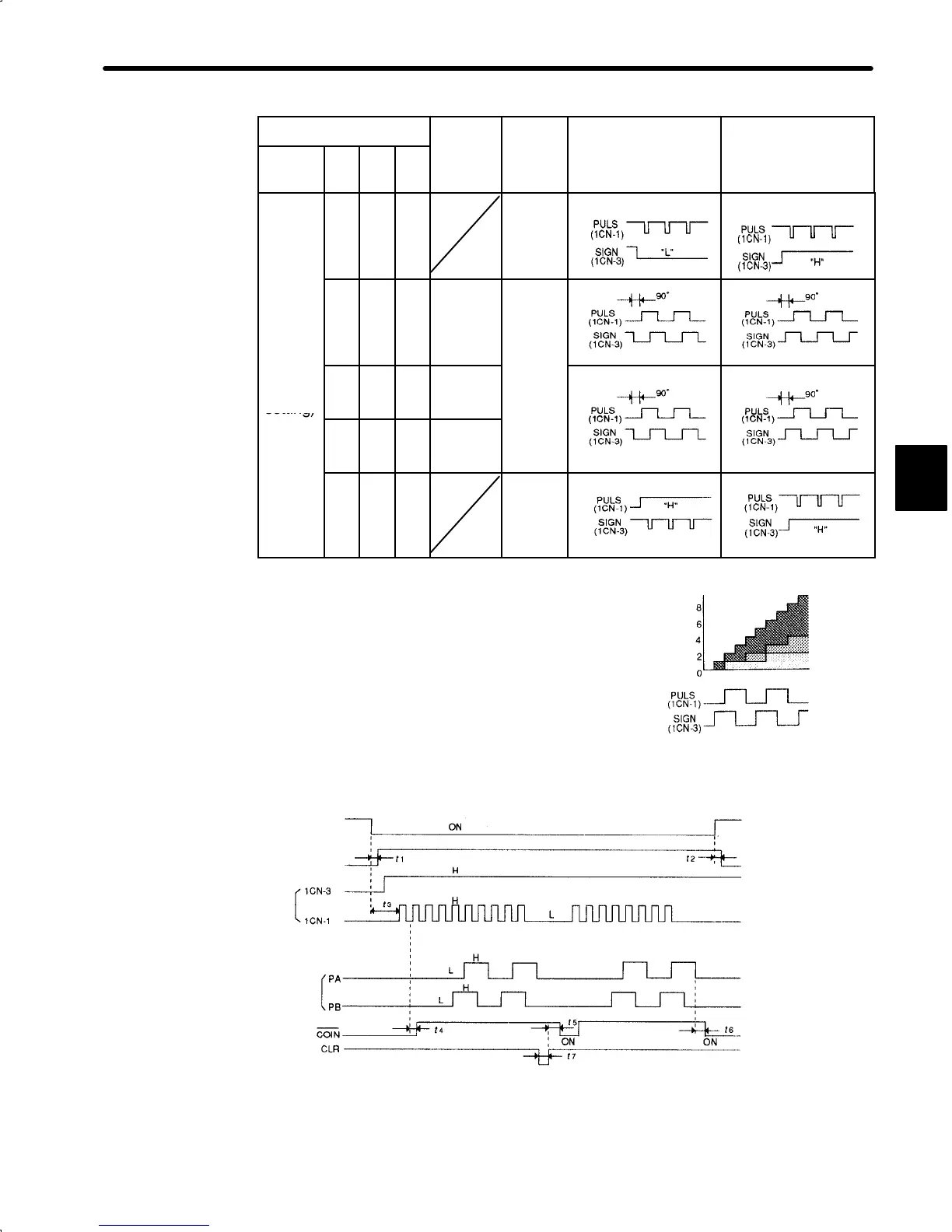
Input Pulse Multiply Function:
When the reference form is two-phase pulse
train with 90° phase difference, the input pulse
multiply function can be used.
The electronic gear function can also be used
to convert input pulses.
Example of I/O Signal Generation Timing
Servo ON
Base block
Sign +
pulse train
Release
t1 ≤ 30 ms
t2 ≤ 6ms
(When user
constant Cn-12 is
set to 0)
t3 ≥ 40 ms
PG pulse
t4, t5, t6 ≤ 2ms
t7 ≥ 20 μs
Note The interval from the time the servo ON signal is turned ON until a reference pulse is
input must be at least 40 ms. Otherwise, the reference pulse may not be input.
The error counter clear (CLR) signal must be ON for at least 20 μs. Otherwise, it be-
comes invalid.
3
Number of
motor move
pulses
x4
x2
x1
Input reference pulse
 Loading...


