APPLICATIONS OF Σ-SERIES PRODUCTS
3.2.5 Using Electronic Gearcont.
82
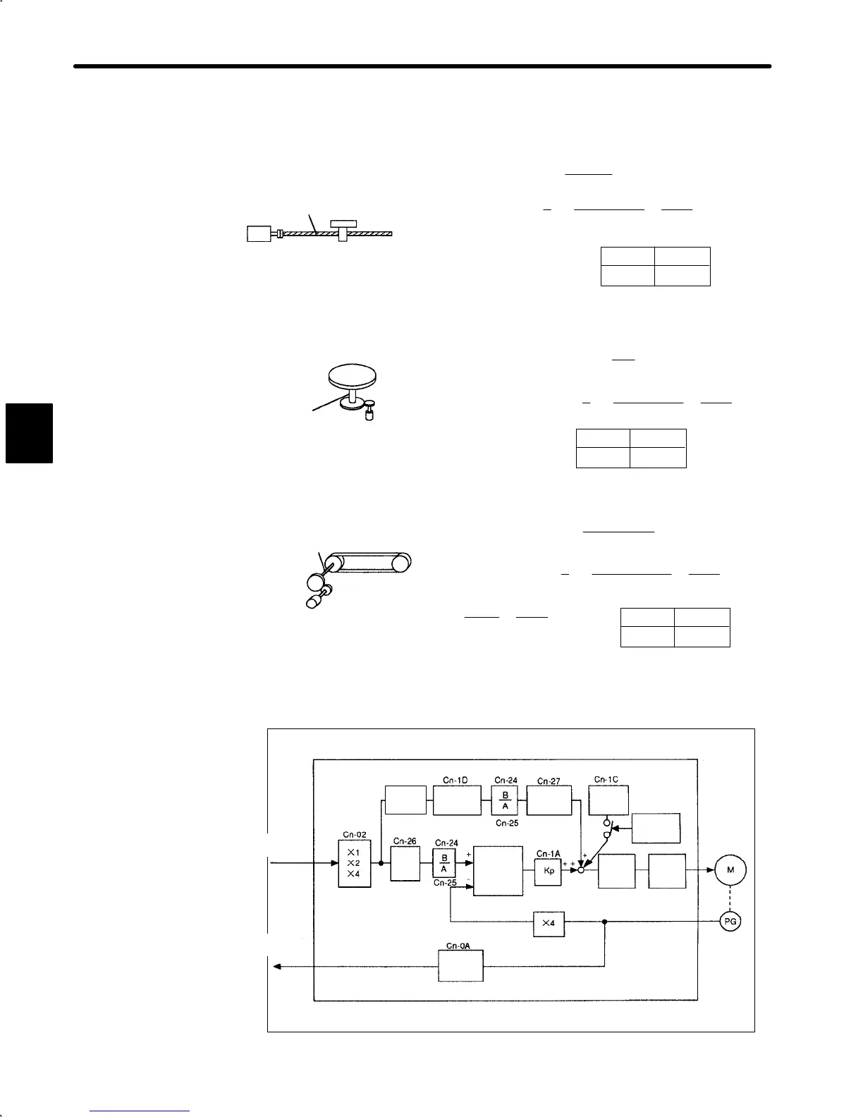
3) Examples of Setting an Electronic Gear Ratio for Different Load Mechanisms
Ball Screw
Reference unit: 0.001 mm
Load shaft
Incremental
encoder:
Ball screw
pitch: 6 mm
Travel distance per
revolution of load shaft
Electronic gear ratio
Preset
values
Cn-24
Cn-25
B
A
=
2048 × 4 × 1
6000 × 1
=
Cn-24
Cn-25
=
6mm
0.001mm
= 6000
8192
6000
2048 pulses per revolution
Disc Table
Reference unit:
0.1°
Gear ratio:
3:1
Load shaft
Incremental encoder:
2048 pulses per revolution
Travel distance per
revolution of load shaft
Preset
values
24576
3600
Cn-24
Cn-25
0.1°
360°
=
= 3600
Electronic gear ratio
B
A
=
2048 × 4 × 3
3600 × 1
=
Cn-24
Cn-25
Belt & Pulley
Pulley diameter:
100 mm
Absolute encoder:
1024 pulses per revolution
Cn-24
Cn-25
Load shaft
Reference unit: 0.0254 mm
Gear ratio:
2.4 : 1
Travel distance per
revolution of load shaft
=
3.14 x 100mm
0.0254mm
= 12362
Electronic gear ratio
B
A
=
1024 × 4 × 2.4
12362 × 1
=
Cn-24
Cn-25
49152
61810
=
9830.4
12362
=
49152
61810
Preset
values
4) Control Block Diagram for SGDA-jjjP Servopack for Position Control
SGDA Servopack for position control
Feed-forw
ard gain
Primary
lag filter
Bias
COIN
signal
Speed
loop
Current
loop
SGM
Servomotor
Encoder
Error
counter
Frequency
dividing
Smoot
hing
Differ-
entiation
Reference
pulse
PG signal
output
3
 Loading...


