INSPECTION, MAINTENANCE, AND TROUBLESHOOTING
6.2.1 Troubleshooting Problems with Alarm Display cont.
394
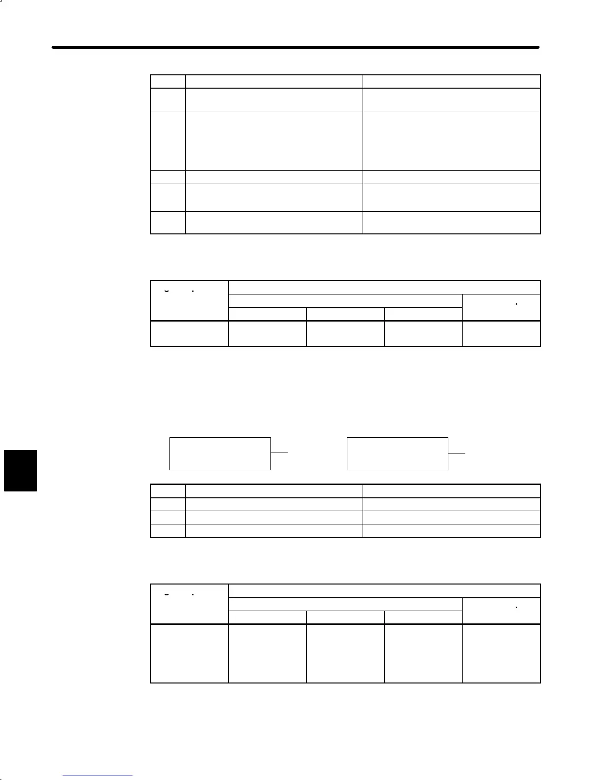
Cause Remedy
A Wiring grounded between Servopack and
servomotor.
Check and correct wiring.
B Servopack ambient temperature exceeds
55°C
Bring Servopack ambient temperature to
55°C
Note Alarm cannot be reset while power
transistor module temperature ex-
ceeds 90°C.
C Servomotor U, V, or W phase grounded. Replace servomotor.
D
• Circuit board (1PWB) defective
• Power transistor defective
Replace Servopack.
E Current feedback circuit, power transistor,
DB relay, or circuit board defective.
Replace Servopack.
D Display and Outputs
Digital Operator
Alarm Output
Display and
Alarm Code Output
Alarm Output
arm
ame
ALO1 ALO2 ALO3
A.20
Fuse blown
OFF ON OFF OFF
OFF: Output transistor is OFF
ON: Output transistor is ON
Status When Alarm Occurred
A
At control power ON
At main circuit power ON
B, C
Cause Remedy
A Circuit board (1PWB) defective Replace Servopack.
B Fuse is blown. Replace Servopack.
C Main circuit diode module defective Replace Servopack.
D Display and Outputs
Digital Operator
Alarm Output
Display and
Alarm Code Output
Alarm Output
arm
ame
ALO1 ALO2 ALO3
A.31
Position error
pulse overflow
(position control
only)
ON ON OFF OFF
OFF: Output transistor is OFF
ON: Output transistor is ON
6

 Loading...


