5 Operation
5.8.3 Torque Limiting Using an Analog Voltage Reference
5-62
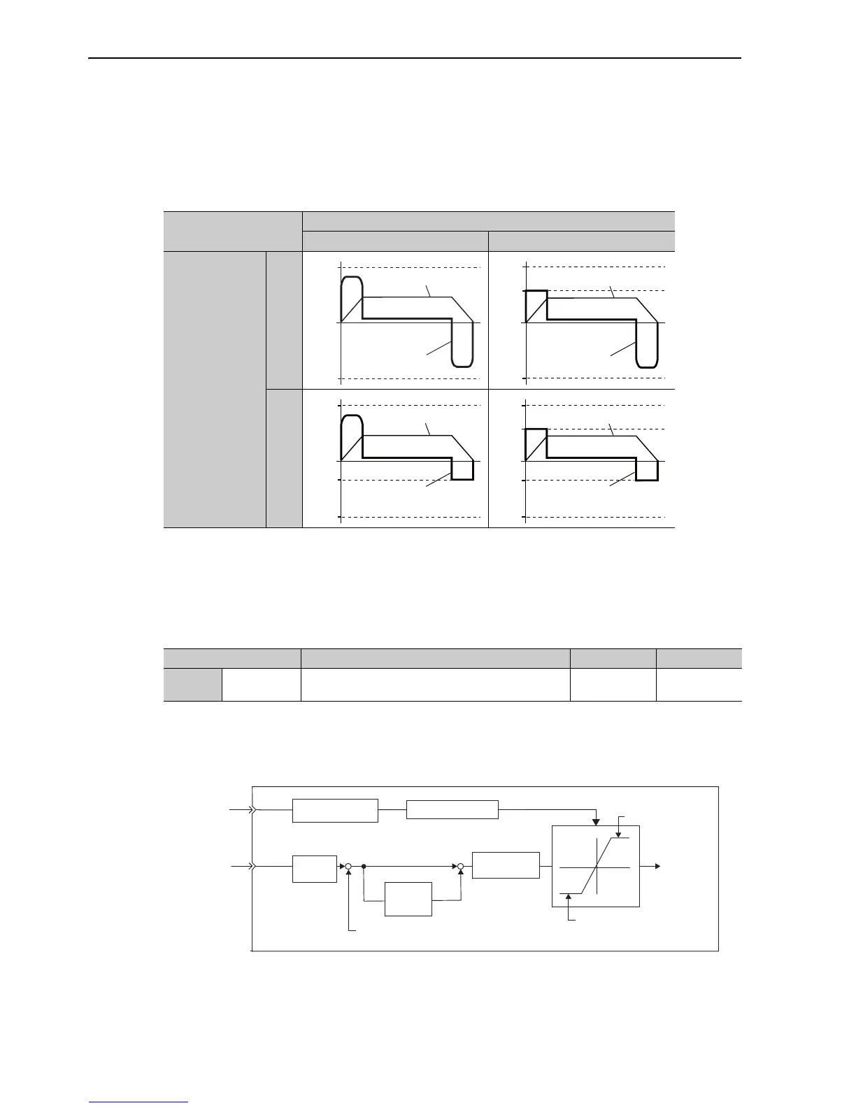
(3) Changes in Output Torque during External Torque Limiting
Changes in output torque when external torque limit is set to 800% are shown with the waveform of Un mon-
itor or SigmaWin+.
In this example, the servomotor rotation direction is Pn000.0 = 0 (CCW = forward).
Note: The waveform reverses in case of analog monitor (CN5) output.
5.8.3 Torque Limiting Using an Analog Voltage Reference
Torque limiting by analog voltage reference limits torque by assigning a torque limit in an analog voltage to
the T-REF terminals (CN1-9 and 10).
This function can be used only during speed or position control, not during torque control.
The following chart shows when the torque limiting using an analog voltage reference in the speed control.
There is no polarity in the input voltage of the analog voltage reference for torque limiting. The absolute val-
ues of both + and - voltages are input, and a torque limit value corresponding to that absolute value is applied
in the forward and reverse direction.
/P-CL (Forward external torque limit input)
OFF ON
/N-CL
(Reverse external
torque limit input)
OFF
ON
0
Pn403
Pn405
Pn402
Torque
Speed
0
Pn403
Pn405
Pn404
Pn402
Torque
Speed
Parameter Meaning When Enabled Classification
Pn002 n.1
Speed control option: Uses the T-REF terminal to be
used as an external torque limit input.
After restart Setup