Home
YASKAWA
Servo Drives
SGMPS
Page 25 (Three-Phase 200 V, SGDV-R70 A01 A, -R90 A01 A, -1 R6 A01 A Models)
YASKAWA SGMPS - Three-Phase 200 V, SGDV-R70 A01 A, -R90 A01 A, -1 R6 A01 A Models; Three-Phase 200 V, SGDV-2 R8 A01 A Model
400 pages
Manual
Save Page as PDF
To Next Page
To Next Page
To Previous Page
To Previous Page
Loading...
1 Outline
1.4.3 Three-phase 200 V
, SGDV
-R
70A01A, -R90A01A, -1R6A01A Models
1-8
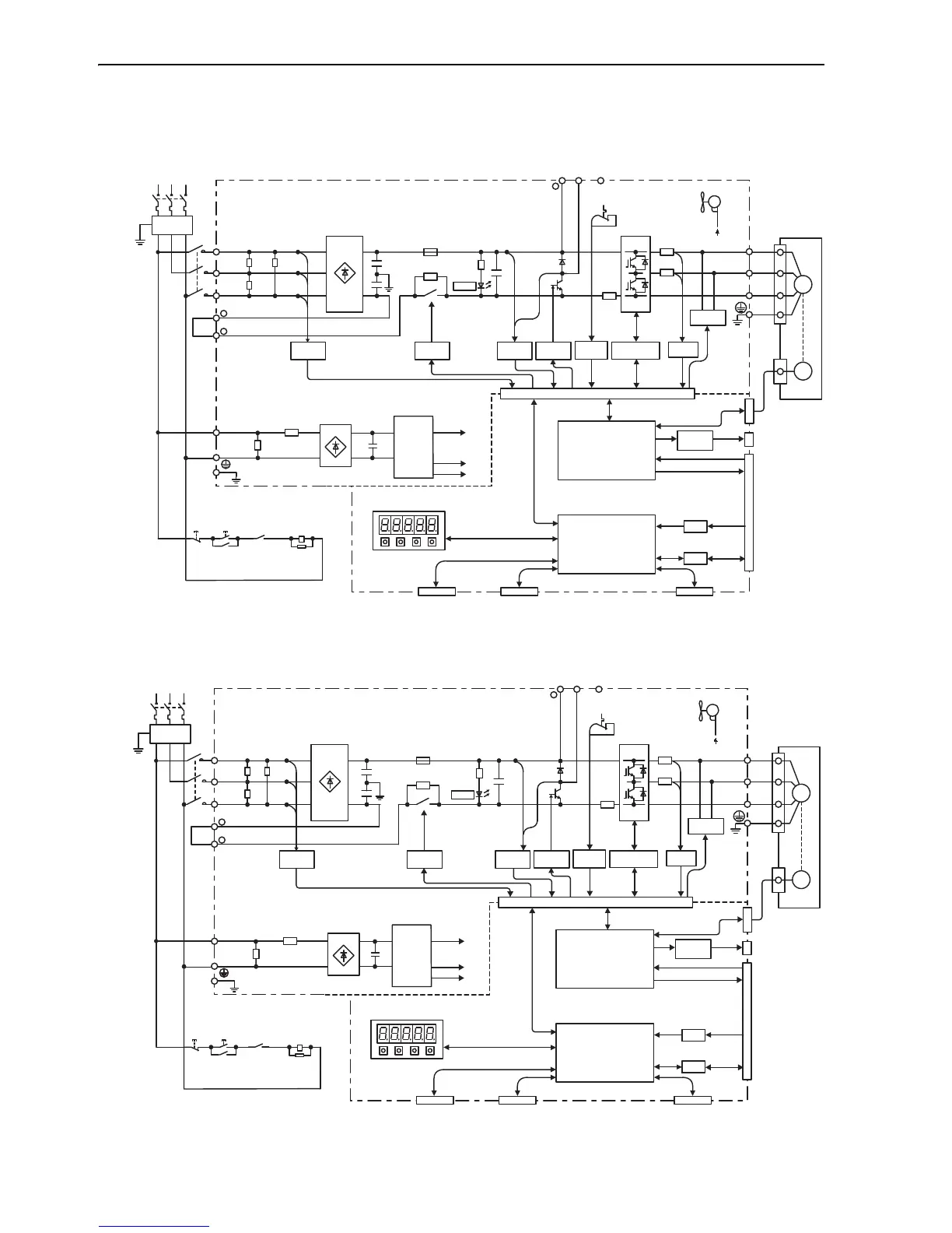
1.4.3
Three-phase 200 V
, SGDV
-R70A0
1A, -R90A01A, -1R
6A01A Models
1.4.4
Three-phase 200 V
, SGDV
-2R8A01A Model
1KM
L1
B1/
B2
B3
L2
L3
1
2
L1C
L2C
U
V
W
+17V
±
12V
+5V
CN3
CN7
1KM
1KM
1Ry
CN2
ENC
A/D
I/O
CN1
CN5
M
+
−
+
−
CHARGE
−
+
−
CN8
Three-phase
200 to 230 V
(50/60 Hz)
+10%
−
15%
Noise
filter
Current
sensor
Dynamic
brake circuit
Surge
absorber
Power
OFF
Power
ON
Open during
servo alarm
Servomotor
Gate
drive
V
oltage
sensor
V
oltage
sensor
V
aristor
V
aristor
Gate drive
overcurrent
protector
T
emperature
sensor
Relay
drive
Fan
ASIC
(PWM control, etc.)
CPU
(Position/speed
calculation, etc.)
Panel operator
Digital operator
Encoder output
pulse
Analog monitor
output
Reference pulse
input
Speed/torque
reference input
I/O signal
Analog
voltage
converter
Personal
computer
Signal for safety fuction
Control
power
supply
+
12 V
1KM
L1
B1/
B2
B3
L2
L3
1
2
L1C
L2C
U
V
W
+17V
±
12V
+5V
CN3
CN7
1KM
1KM
1Ry
CN2
ENC
A/D
I/O
CN1
CN5
M
+
−
CHARGE
−
+
CN8
+
−
−
Three-phase
200 to 230 V
(50/60 Hz)
+10%
−
15%
Noise
filter
Current
sensor
Dynamic
brake circuit
Surge
absorber
Power
OFF
Power
ON
Open during
servo alarm
Servomotor
Gate
drive
Vo
lt
a
g
e
sensor
V
oltage
sensor
V
aristor
V
aristor
Gate drive
overcurrent
protector
T
emperature
sensor
Relay
drive
Fan
ASIC
(PWM control, etc.)
CPU
(Position/speed
calculation, etc.)
Panel operator
Digital operator
Encoder output
pulse
Analog monitor
output
Reference pulse
input
Speed/torque
reference input
I/O signal
Analog
voltage
converter
Personal
computer
Signal for safety fuction
Control
power
supply
+
12 V
24
26
Table of Contents
Main Page
Default Chapter
3
About this Manual
3
Safety Precautions
6
Applicable Standards
11
Table of Contents
12
Chapter 1 Outline
19
Σ-V Series Servopacks
19
Part Names
19
SERVOPACK Ratings and Specifications
20
Ratings
20
Basic Specifications
21
Speed/Position/Torque Control Modes
23
SERVOPACK Internal Block Diagrams
24
Single-Phase 100 V, SGDV-R70F01A, -R90F01A, -2R1F01A Models
24
Single-Phase 100 V, SGDV-2R8F01A Model
24
Three-Phase 200 V, SGDV-R70A01A, -R90A01A, -1R6A01A Models
25
Three-Phase 200 V, SGDV-2R8A01A Model
25
Three-Phase 200 V, SGDV-3R8A01A, -5R5A01A, -7R6A01A Models
26
Three-Phase 200 V, SGDV-120A01A Model
26
Three-Phase 200 V, SGDV-180A01A, -200A01A Models
27
Three-Phase 200 V, SGDV-330A01A Model
27
Three-Phase 200 V, SGDV-470A01A, -550A01A Models
28
Three-Phase 200 V SGDV-590A01A, -780A01A Models
28
Three-Phase 400 V, SGDV-1R9D01A, -3R5D01A, -5R4D01A Models
29
Three-Phase 400 V, SGDV-8R4D01A, -120D01A Models
29
Three-Phase 400 V, SGDV-170D01A Model
30
Three-Phase 400 V, SGDV-210D01A, -260D01A Models
30
Three-Phase 400 V SGDV-280D01A, -370D01A Models
31
Examples of Servo System Configurations
32
Connecting to SGDV- F01A SERVOPACK
32
A01A Servopack
33
D01A Servopack
34
SERVOPACK Model Designation
35
Inspection and Maintenance
36
Chapter 2 Panel Operator
38
Panel Operator
38
Display Mode Selection
38
Status Display Mode
39
Utility Function Mode (Fn )
40
How to Read a Parameter Explanation
41
Explanation Method for Parameter Setting Type
41
Explanation Method for Function Selection Type
41
Explanation Method for Tuning Parameters
42
Parameter Setting Mode (Pn )
43
Parameter Setting Mode for Parameter Setting Type
43
Parameter Setting Mode for Function Selection Type
46
Monitor Mode (un )
47
Chapter 3 Wiring and Connection
49
Main Circuit Wiring
49
Names and Functions of Main Circuit Terminals
50
SERVOPACK Main Circuit Wire Size
51
Typical Main Circuit Wiring Examples
52
General Precautions for Wiring
56
Precautions When Using the SERVOPACK with a DC Power Input
57
Precautions When Using the SERVOPACK with Single-Phase, 200 V Power Input
59
Precautions When Using more than One SERVOPACK
62
I/O Signal Connections
63
I/O Signal (CN1) Names and Functions
63
I/O Signal Connector (CN1) Terminal Layout
65
Safety Function Signal (CN8) Names and Functions
66
Example of I/O Signal Connections in Speed Control
67
Example of I/O Signal Connections in Position Control
68
Example of I/O Signal Connections in Torque Control
69
I/O Signal Allocations
70
Input Signal Allocations
70
Output Signal Allocations
74
Examples of Connection to Host Controller
78
Reference Input Circuit
78
Sequence Input Circuit
80
Sequence Output Circuit
81
Examples of Encoder Connection
83
Connection Example of an Encoder
83
CN2 Encoder Connector Terminal Layout
84
Connecting Regenerative Resistors
85
Setting Regenerative Resistor Capacity
87
Noise Control and Measures for Harmonic Suppression
88
Wiring for Noise Control
88
Precautions on Connecting Noise Filter
90
Connecting AC/DC Reactor for Harmonic Suppression
92
Chapter 4 Trial Operation
94
Inspection and Checking before Trial Operation
94
Trial Operation for Servomotor Without Load
94
Trial Operation for Servomotor Without Load from Host Reference
95
Inspecting Connection and Status of Input Signal Circuits
97
Trial Operation in Speed Control
99
Trial Operation under Position Control from the Host with the SERVOPACK Used for Speed Control
100
Trial Operation in Position Control
101
Trial Operation with the Servomotor Connected to the Machine
102
Trial Operation of Servomotor with Brakes
103
Test Without Motor Function
104
Related Parameters
104
Limitations
104
Operating Procedure
106
Operator Display During Testing Without Motor
107
Chapter 5 Operation
108
Control Selection
110
Setting Common Basic Functions
111
Servo on Signal
111
Servomotor Rotation Direction
112
Overtravel
113
Holding Brakes
115
Stopping Servomotors after /S_ON Turned off or Alarm Occurrence
120
Instantaneous Power Interruption Settings
122
SEMI F47 Function (Torque Limit Function for Low Power Supply Voltage for Main Circuit)
123
Setting Motor Overload Detection Level
126
Operating Using Speed Control with Analog Voltage Reference
128
Basic Settings for Speed Control
128
Reference Offset Adjustment
130
Soft Start
132
Speed Reference Filter
133
Zero Clamp Function
134
Encoder Output Pulses
137
Encoder Output Pulse Setting
138
Encoder Output Pulses
138
Speed Coincidence Signal Setting
139
Operating Using Position Control with Pulse Train Reference
140
Basic Settings for Position Control Mode
140
Clear Signal
145
Electronic Gear
146
Smoothing
149
Positioning Completed Output Signal
150
Positioning Near Signal
151
Reference Pulse Inhibit Function
152
Operating Using Torque Control with Analog Voltage Reference
154
Basic Settings for Torque Control Mode
154
Reference Offset Adjustment
155
Torque Reference Filter
158
Speed Limit in Torque Control
158
Operating Using Speed Control with an Internal Set Speed
160
Basic Settings for Speed Control with an Internal Set Speed
160
Example of Operating with Internal Set Speed
162
Combination of Control Modes
163
Switching Internal Set Speed Control (Pn000.1 = 4, 5, or 6)
164
Switching Other than Internal Set Speed Control (Pn000.1 = 7, 8 or 9)
166
Switching Other than Internal Set Speed Control (Pn000.1 = a or B)
166
Limiting Torque
167
Internal Torque Limit
167
External Torque Limit
168
Torque Limiting Using an Analog Voltage Reference
169
Torque Limiting Using an External Torque Limit and Analog Voltage Reference
170
Checking Output Torque Limiting During Operation
171
Absolute Encoders
172
Encoder Resolutions
172
Standard Connection Diagram and Setting the Absolute Data Request Signal (SEN)
173
Absolute Encoder Data Backup
174
Battery Replacement
175
Absolute Encoder Setup
177
Absolute Encoder Reception Sequence
178
Multiturn Limit Setting
181
Multiturn Limit Disagreement Alarm (A.CC0)
182
Other Output Signals
183
Servo Alarm Output Signal (ALM) and Alarm Code Output Signals (ALO1, ALO2, and ALO3)
183
Warning Output Signal (/WARN)
184
Rotation Detection Output Signal (/TGON)
185
Servo Ready Output Signal (/S-RDY)
185
Safety Function
186
Hard Wire Base Block (HWBB) Function
186
External Device Monitor (EDM1)
190
Application Example of Safety Functions
192
Confirming Safety Functions
193
Precautions for Safety Functions
194
Chapter 6 Adjustments
195
Adjustments and Basic Adjustment Procedure
197
Adjustments
197
Basic Adjustment Procedure
199
Monitoring Analog Signals
200
Safety Precautions on Adjustment of Servo Gains
202
Tuning-Less Function
205
Tuning-Less Levels Setting (Fn200) Procedure
208
Advanced Autotuning (Fn201)
211
Advanced Autotuning
211
Advanced Autotuning Procedure
214
Related Parameters
220
Advanced Autotuning by Reference (Fn202)
221
Advanced Autotuning by Reference
221
Advanced Autotuning by Reference Procedure
224
Related Parameters
228
One-Parameter Tuning (Fn203)
229
One-Parameter Tuning
229
One-Parameter Tuning Procedure
231
One-Parameter Tuning Example
237
Related Parameters
238
Anti-Resonance Control Adjustment Function (Fn204)
239
Anti-Resonance Control Adjustment Function
239
Anti-Resonance Control Adjustment Function Operating Procedure
240
Related Parameters
244
Vibration Suppression Function (Fn205)
245
Vibration Suppression Function
245
Vibration Suppression Function Operating Procedure
246
Related Parameters
249
Additional Adjustment Function
250
Switching Gain Settings
250
Friction Compensation
255
Friction Compensation
256
Current Control Mode Selection
257
Current Gain Level Setting
257
Speed Detection Method Selection
257
Compatible Adjustment Function
258
Feedforward Reference
258
Torque Feedforward
259
Speed Feedforward
260
Proportional Control Operation (Proportional Operation Reference)
261
Using the Mode Switch (P/PI Switching)
262
Torque Reference Filter
267
Position Integral Time Constant
268
Chapter 7 Utility Functions (Fn )
269
List of Utility Functions
270
Alarm History Display (Fn000)
271
JOG Operation (Fn002)
272
Origin Search (Fn003)
273
Program JOG Operation (Fn004)
275
Initializing Parameter Settings (Fn005)
280
Clearing Alarm History (Fn006)
281
Offset Adjustment of Analog Monitor Output (Fn00C)
282
Gain Adjustment of Analog Monitor Output (Fn00D)
284
Automatic Offset-Signal Adjustment of the Motor Current Detection
286
Automatic Offset-Signal Adjustment of the Motor Current
286
Detection (Fn00F)
287
Manual Offset-Signal Adjustment of the Motor Current
287
Fn00E
288
Manual Offset-Signal Adjustment of the Motor Current Detection (Fn00F)
288
Write Prohibited Setting (Fn010)
288
Servomotor Model Display (Fn011)
290
Software Version Display (Fn012)
291
Resetting Configuration Error of Option Module (Fn014)
292
Vibration Detection Level Initialization (Fn01B)
293
Display of SERVOPACK and Servomotor ID (Fn01E)
295
Display of Servomotor ID in Feedback Option Module (Fn01F)
296
Origin Setting (Fn020)
297
Software Reset (Fn030)
298
Easyfft (Fn206)
299
Online Vibration Monitor (Fn207)
303
Chapter 8 Monitor Modes (un )
306
List of Monitor Modes
306
Operation in Monitor Mode
307
Reading 32-Bit Decimal Displays
308
Monitoring Input Signals
309
Displaying Input Signal Status
309
Interpreting Input Signal Display Status
309
Input Signal Display Example
310
Monitoring Safety Input Signals
311
Interpreting Safety Input Signal Display Status
311
Safety Input Signal Display Example
311
Monitoring Output Signals
312
Displaying Output Signal Status
312
Interpreting Output Signal Display Status
312
Output Signal Display Example
312
Monitor Display at Power on
313
Chapter 9 Fully-Closed Loop Control
314
System Configuration and Connection Example for SERVOPACK with Fully-Closed Loop Control
315
Fully-Closed Loop Control
315
System Configuration
315
Internal Configuration of Fully-Closed Loop Control
316
Serial Converter Unit
317
Connection Example of External Encoder by Heidenhain
319
Connection Example of External Encoder by Mitutoyo
320
Connection Example of External Encoder by Renishaw
321
Encoder Output Pulse Signals from SERVOPACK with a External Encoder by Renishaw
322
Settings for Fully-Closed Loop Control
323
Setting Order
323
Motor Rotation Direction
324
Sine Wave Pitch (Frequency) for an External Encoder
326
Number of Encoder Output Pulses (PAO, PBO, and PCO) from the SERVOPACK
326
Absolute External Encoder Reception Sequence
327
Electronic Gear
330
Alarm Detection
330
Analog Monitor Signal
331
Speed Feedback Method During Fully-Closed Loop Control
332
Troubleshooting
333
Chapter 10 Troubleshooting
333
List of Alarms
334
Troubleshooting
334
Troubleshooting of Alarms
338
Warning Displays
352
List of Warnings
352
Troubleshooting of Warnings
353
Warning Displays
353
Troubleshooting Malfunction Based on Operation and Conditions of the Servomotor
356
Chapter 11 Appendix
361
Connection to Host Controller
362
Example of Connection to MP2200/MP2300 Motion Module SVA-01
362
Example of Connection to MP920 4-Axes Analog Module SVA-01
363
Example of Connection to Omron's Motion Control Unit
364
Example of Connection to Omron's Position Control Unit
365
Connection to Mitsubishi's AD72 Positioning Unit (SERVOPACK in Speed Control Mode)
366
Connection to Mitsubishi's AD75 Positioning Unit (SERVOPACK in Position Control Mode)
367
Connection to Mitsubishi's AD75 Positioning Unit
367
(SERVOPACK in Position Control Mode)
367
List of Parameters
369
Parameters
370
List of Parameters
371
Parameters
372
Monitor Modes
389
Parameter Recording Table
390
Index
395
Revision History
399
Related product manuals
YASKAWA SGMGV
400 pages
YASKAWA SGM7E
172 pages
YASKAWA SGMJV
400 pages
YASKAWA SGM7M
55 pages
YASKAWA SGM7G
337 pages
YASKAWA SGMSV
378 pages
YASKAWA SGMGH
615 pages
YASKAWA SGM7J
337 pages
YASKAWA SGMAH
488 pages
YASKAWA SGM-A3
513 pages
YASKAWA SGM7J-A5A
622 pages
YASKAWA E-II SGM H Series
408 pages