5.4 Operating Using Position Control with Pulse Train Reference
This section describes the operation in position control with pulse train reference.
Select the position control with Pn000.
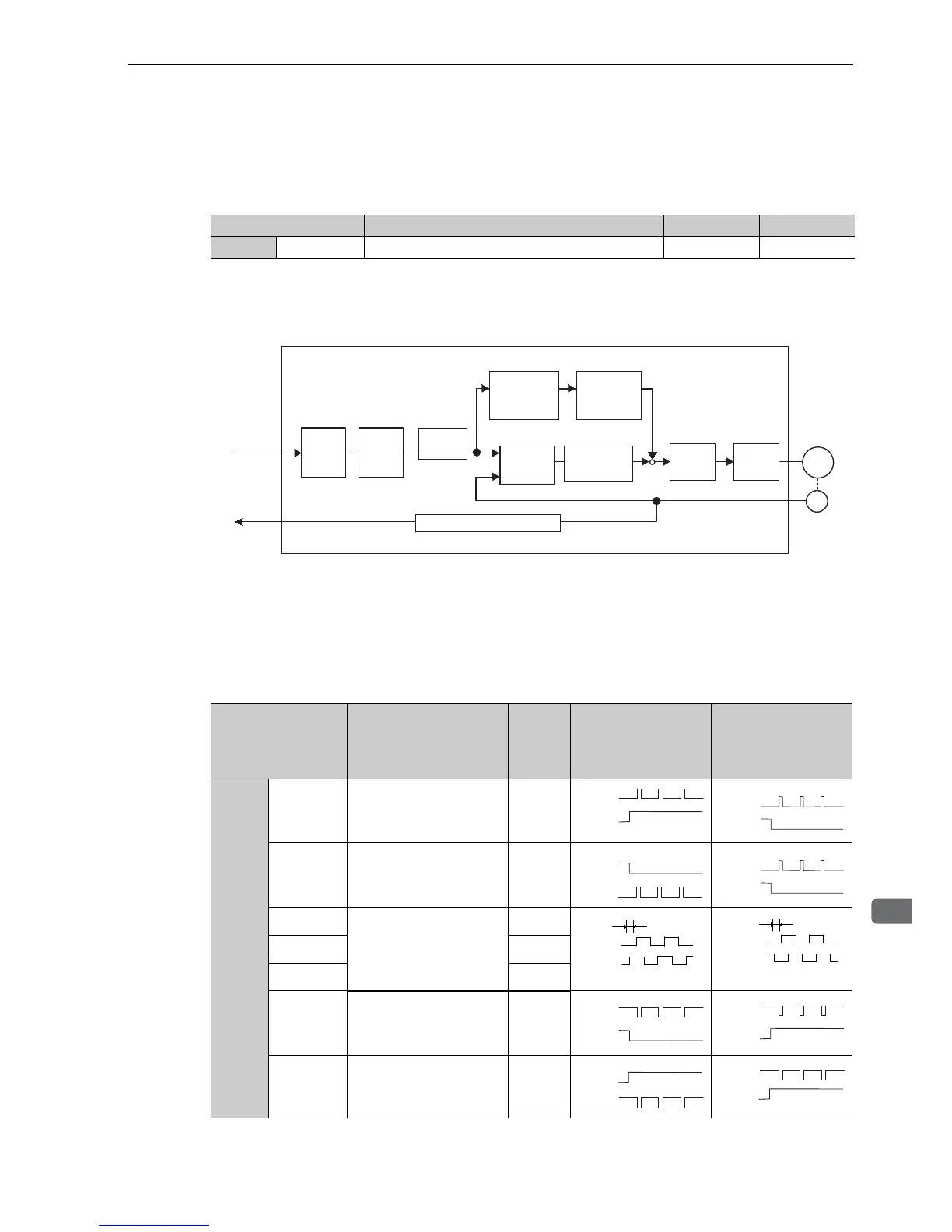
Block Diagram for Position Control
A block diagram for position control is shown below.
5.4.1 Basic Settings for Position Control Mode
Set the following signal and parameter for position control with pulse train reference.
(1) Pulse Reference Input Signal Form
Set the pulse reference input signal form using Pn200.0.
Parameter Meaning When Enabled Classification
Pn000 n.1 Control mode: Position control (pulse train reference) After restart Setup
Encoder
output pulse
Reference
pulse
SERVOPACK (in position control)
Pn216
Pn217
M
Pn212
Pn210
Pn20E
+
−
Pn102
ENC
Pn200.0
+
+
Pn109
Pn10A
Reference
pulse
form
Electronic
gear
ratio
Smoothing
Feedforward
Error
counter
Encoder output pulse
Position
loop gain
Speed
control
Current
control
Servomotor
Encoder
Feedforward
filter