Note 1. After turning the power ON, turn ON the SEN signal after ALM signal is turned OFF and then ON.
2. When the SEN signal changes from low level to high level, the rotational data and initial incremental pulses are
output.
Until these operations have been completed, the motor cannot be operated regardless of the status of the servo
ON. The panel operator display will also remain "bb."
5.9.3 Absolute Encoder Data Backup
In order for the absolute encoder to retain position data when the power is turned OFF, the data must be
backed up by a battery.
Install the battery in the host controller or the SERVOPACK.
Installing the Battery at the Host Controller
Connect the battery to the host controller, referring the following diagram. Use an ER6VC3 battery (3.6 V, 200
mAh: manufactured by Toshiba Battery Co., Ltd.) or an equivalent.
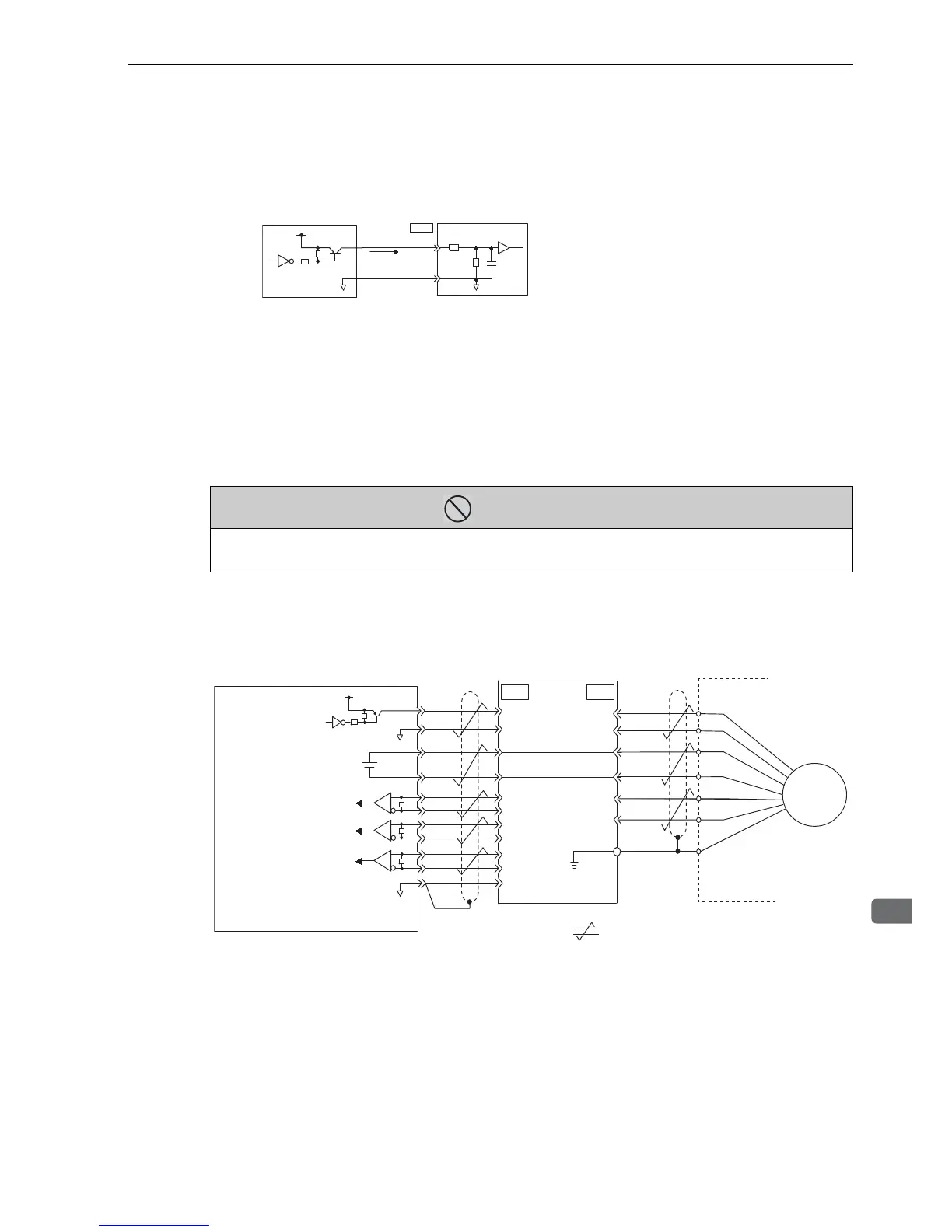
4.7 k
SEN
4
CN1
SG
2
+5V
0V
100 Ω
Ω
0V
0.1 μ(
Host controller
SERVOPACK
High level:
About 1 mA
7406
or equivalent
We recommend a PNP transistor.
Signal levels
High: 4.0 V min., Low: 0.8 V max.
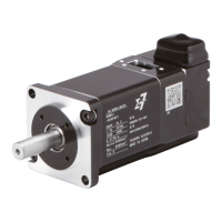
PROHIBITED
• Do not install the battery at both the host controller and the SERVOPACK.
It is dangerous because a loop circuit between the batteries is set up.
R
PG5V
PG0V
BA
PS
/PS
T (+)
BAT ( - )
BAT(+)
BAT(-)
-
PCO
/PCO
PBO
/PBO
PA O
/PAO
SEN
SG
R
R
Phase A
Phase B
Phase C
+5V
7406
0V
4
2
21
22
33
34
35
36
19
1
20
CN1
1
2
3
4
6
5
CN2
SG
0V
Host controller SERVOPACK Encoder
Line receiver
: Represents twisted-pair wires.
Sheild (shell)
Connector
shell
Applicable line receiver:
Taxas Instruments’s SN75ALS175 or MC3486
Terminating resistance R: 220 to 470Ω
ENC
∗
∗
∗
Note: Set the SEN signal to low level
when the main circuit power to the
SERVOPACK is turned OFF.
Battery
+