11 Appendix
11.2.2 Parameters
11-30
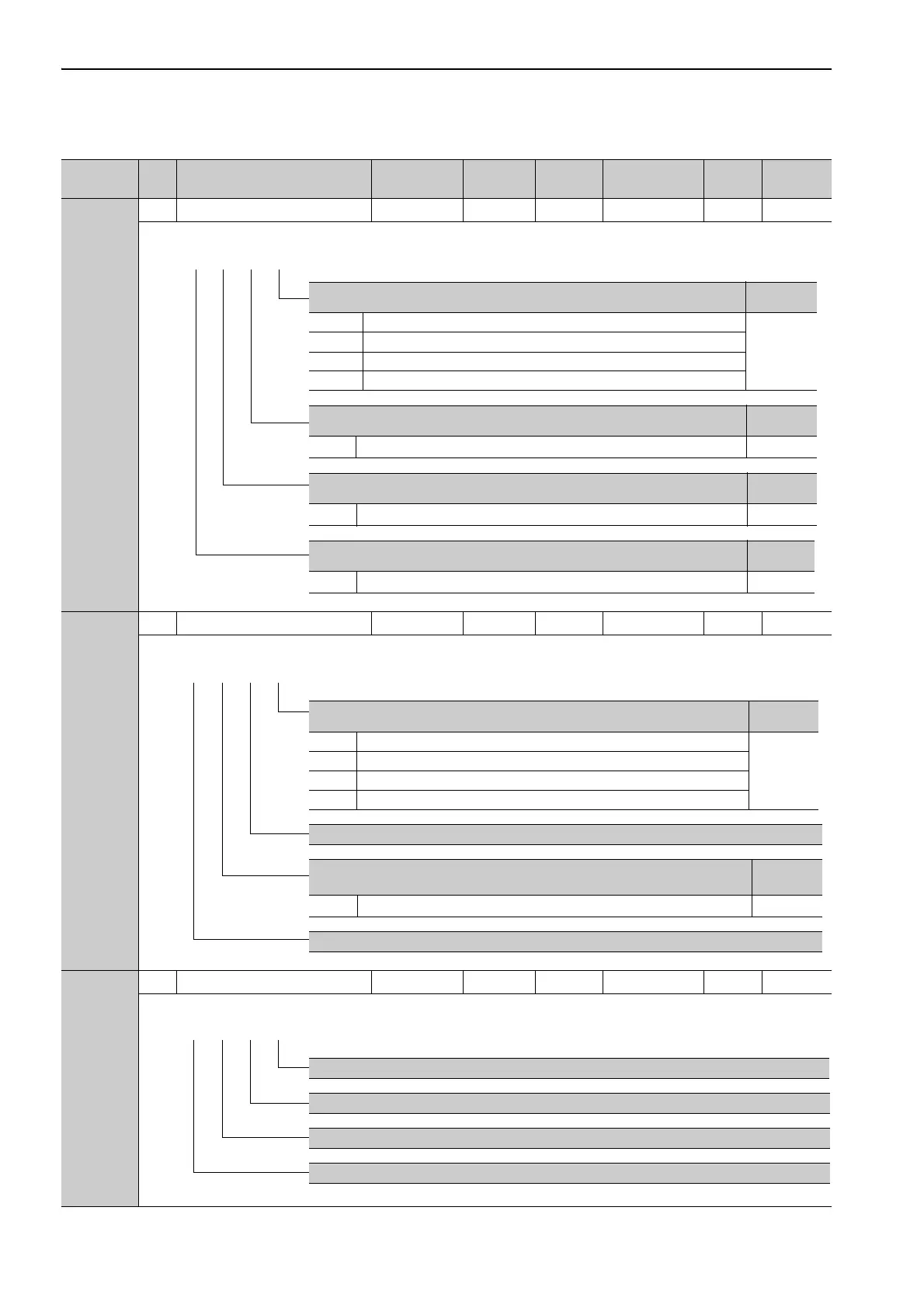
Pn50F
2 Output Signal Selection 2 0000 to 3333 − 0000 After restart Setup −
Pn510
2 Output Signal Selection 3 0000 to 0333 − 0000 After restart Setup −
Pn511
2 Input Signal Selection 5 0000 to FFFF − 8888 After restart Setup −
(cont’d)
Parameter
No.
Size
Name
Setting
Range
Units
Factory
Setting
When Enabled
Classifi-
cation
Reference
Section
Torque Limit Detection Signal Mapping (/CLT)
Reference
Section
0 Disabled (the above signal is not used.)
5.8.5
1 Outputs the signal from CN1-25, -26 output terminal.
2 Outputs the signal from CN1-27, -28 output terminal.
3 Outputs the signal from CN1-29, -30 output terminal.
Speed Limit Detection Signal Mapping (/VLT)
Reference
Section
0 to 3
Same as /CLT Signal Mapping.
5.5.4
Brake Signal Mapping (/BK)
Reference
Section
0 to 3
Same as /CLT Signal Mapping.
5.2.4
Warning Signal Mapping (/WARN)
Reference
Section
0 to 3
Same as /CLT Signal Mapping.
5.10.2
4th 3rd 2nd 1st
digit digit digit digit
n.
Near Signal Mapping (/NEAR)
Reference
Section
0 Disabled (the above signal is not used.)
5.4.7
1 Outputs the signal from CN1-25, -26 output terminal.
2 Outputs the signal from CN1-27, -28 output terminal.
3 Outputs the signal from CN1-29, -30 output terminal.
Reserved (Do not change.)
Reference Pulse Input Multiplication Switching Output Signal Mapping
(/PSELA)
Reference
Section
0 to 3
Same as /NEAR Signal Mapping.
5.4.3
Reserved (Do not change.)
4th 3rd 2nd 1st
digit digit digit digit
n.
Reserved (Do not change.)
Reserved (Do not change.)
Reserved (Do not change.)
Reserved (Do not change.)
4th 3rd 2nd 1st
digit digit digit digit
n.

 Loading...


