L
H
H
CH1
CH2
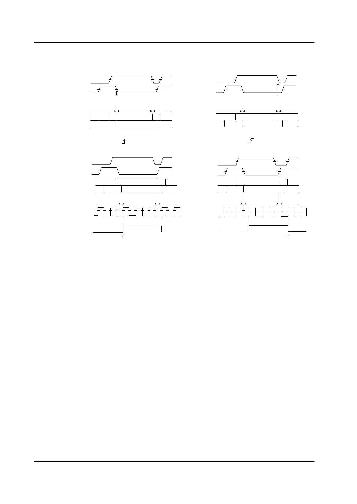
Clock source: None
State: CH1 = H, CH2 = L, other channels = X,
AND logic, Polarity: Enter
Trigger
CH1
CH2
H
H
L
L
L
State condition
not met
State condition
not met
State condition
not met
State condition
not met
State condition
not met
State condition
not met
State condition
met
State condition
met
State condition
met
State condition
met
State condition
not met
State condition
not met
L
H
H
CH1
CH2
Trigger
CH3
CH1
CH2
H
H
L
L
L
L
H
H
CH1
CH2
Clock source: None
State: CH1 = H, CH2 = L, other channels = X,
AND logic, Polarity: Exit
Trigger
CH1
CH2
H
H
L
L
L
Clock source: CH3,
State: CH1 = H, CH2 = L, CH4 = X, AND logic
Porarity: Enter
CH1
CH2
Trigger
CH3
Clock source: CH3,
State: CH1 = H, CH2 = L, CH4 = X, AND logic
Porarity: Exit
Normalized condition
L
H
H
CH1
CH2
H
H
L
L
L
Normalized condition
 Loading...


