3-8
IM 701310-01E
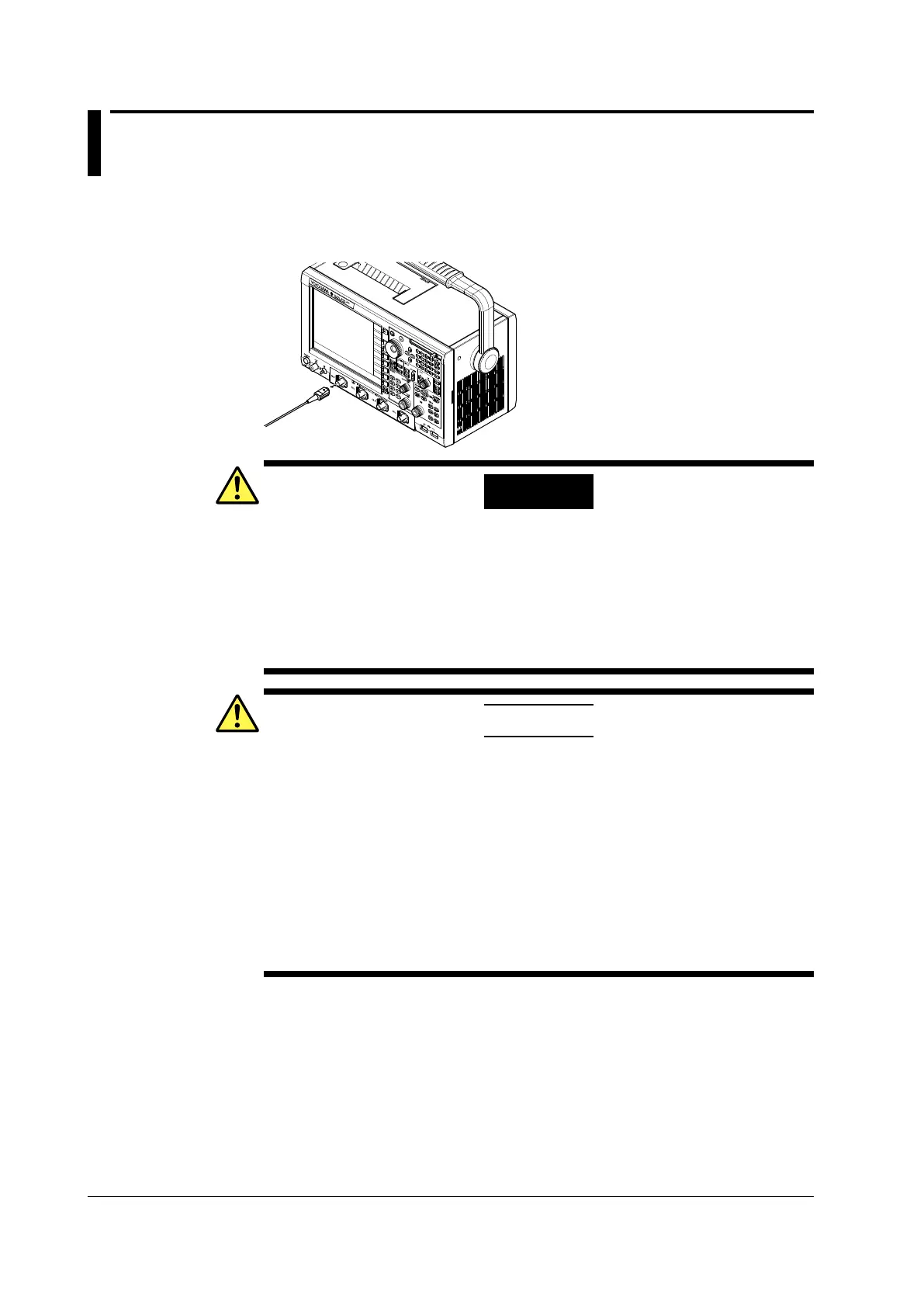
3.4 Connecting the Probe
Connect a probe (or measurement input cable such as a BNC cable) to the input terminal
on the bottom of the front panel. The input impedance is 1 M
W
±
1% and approximately
20 pF or 50
W
±
1.5%.
WARNING
● AlwaysturnOFFthepoweroftheobjecttobemeasuredwhenconnectingitto
this instrument. Connecting or disconnecting a measuring lead while the power
of the object to be measured is ON is extremely dangerous.
● Donotinputexcessivevoltagesthatexceedmaximum input voltage, withstand
voltage, or tolerance surge voltage.
● Alwaysu
se
aprotectground(earth)fortheinstrumenttopreventelectricshocks.
● Avoidcontinuousconnectionsinenvironmentswherethereisthepossibilitythat
tolerance surge voltages can be generated.
CAUTION
● Theprobeinterfaceterminalislocatedneartheinputterminalonthisinstrument.
When connecting the probe, make sure to prevent an excessive voltage due to
static electricity, etc., from being applied to the probe interface terminal, as this
may damage it.
● Thep
robeinterfaceterminalislocatedneartheinputterminalonthisinstrument.
Do not short the probe interface terminal.
● Themaximuminputvoltagefor1M
Ω-
input is 150 Vrms when the frequency
is 1 kHz or less. Applying a voltage exceeding the value can damage the input
section. If the frequency is above 1 kHz, damage may occur even when the
voltage is below the value.
● Themaximuminputvoltagefor50Ω-inputis5Vrmsand10Vpeak.Applying
a
voltage exceeding either of these values can damage the input section.
Precautions to Be Taken When Connecting Cables
• When connecting a probe to the instrument for the first time, perform phase
correction of the probe as described in section 3.5, “Compensating the Probe
(Phase Correction).” If you do not, frequency characteristics will not be flat, and
measurements will not be correct. Perform the phase correction on each channel to
which a probe is to be connected.
• Note that if the object being measured is directly connected to
the instrument without
using a probe, correct measurements may not be possible because of the effect of
input impedance on the instrument. Use caution.
 Loading...


