Making Preparations for Measurements
3-11
IM 701310-01E
3
2
1
4
5
6
7
8
9
10
11
12
13
14
15
16
17
18
19
App
Index
3.5 Compensating the Probe (Phase Correction)
Be sure to perform phase correction of the probe first when using a probe to make
measurements.
CAUTION
Do not apply external voltage to the signal output terminal for probe compensation
adjustment. This may cause damage to the internal circuitry.
Procedure
1.
Turn ON the power switch.
2.
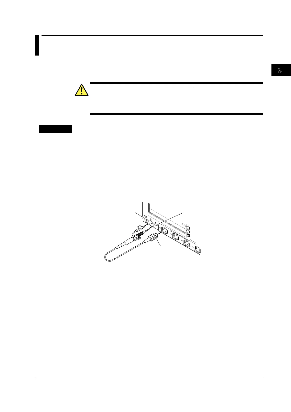
Connect the probe to the input terminal to which the signal is to be applied.
3.
Connect the tip of the probe to the signal output terminal for probe compensation
adjustment on the front panel of the instrument and to the ground wire to the
functional ground terminal.
4.
Perform auto setup according to the procedures given in section 4.5, “Performing
Auto Setup.”
5.
Insert a flat-head screwdriver to the phase adjustment hole and turn the variable
capacitor to make the displayed waveform a correct rectangular wave.
Signal output terminal for probe
compensation adjustment
Functional ground
terminal
Phase adjustment
hole
 Loading...


