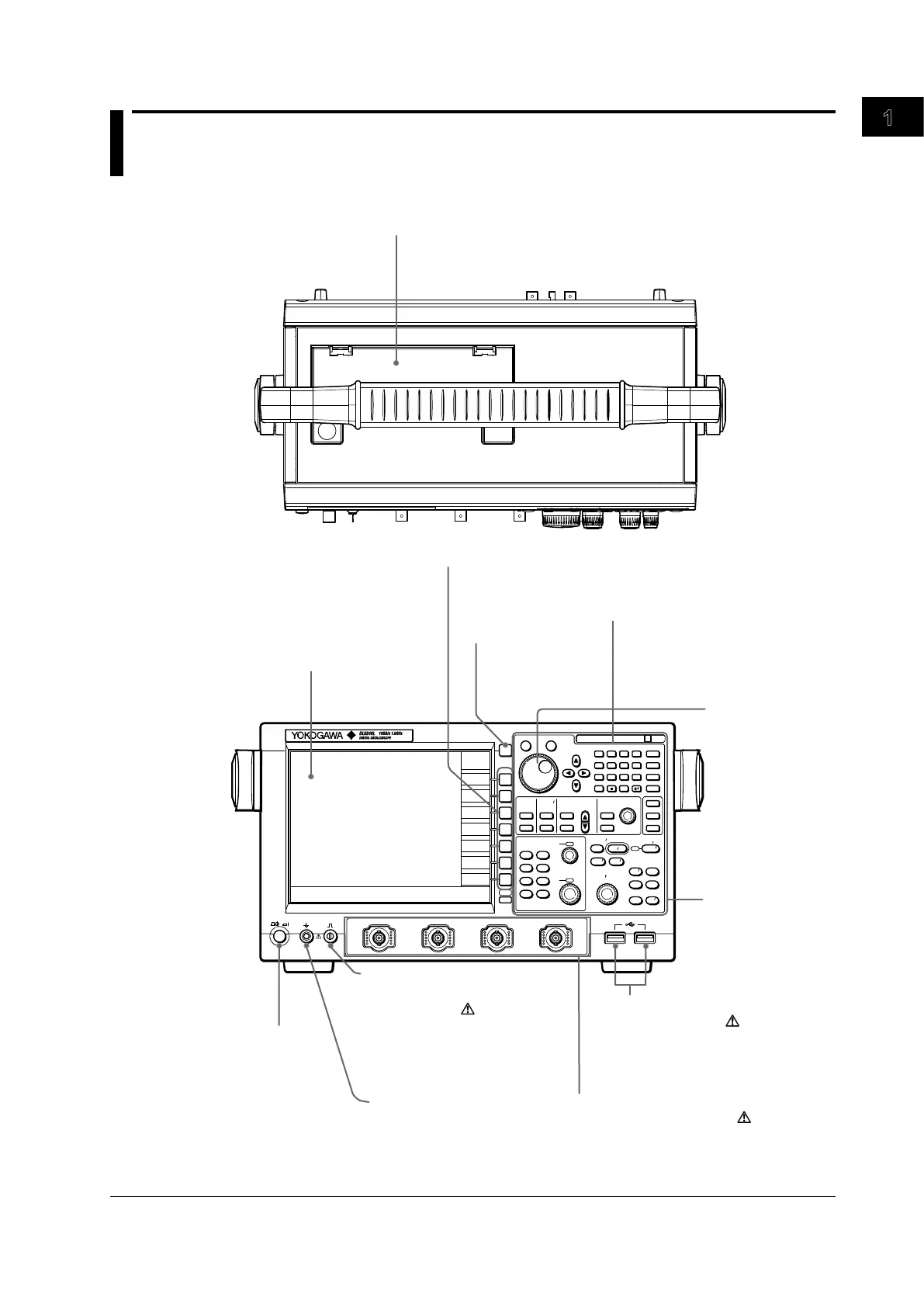
Built-in printer
Prints the display contents.
For installing the paper roll, see section 12.1.
For printing operations, see section 12.2.
ESC
SNAP
SNAP CLEAR
RESET
SET
7 8 9
BS
PRINT
FILE
SHIFT
SYSTEM
EXP
CLEAR
M
MENU
D E F X
k m
u n p
4 5 6
1 2 3
0
+/-
CA B
CURSOR
PARAM
TELECOM
TEST
WINDOW 1
WINDOW 2
FORM
ACCUM
CLEAR
ZOOM 1
ZOOM 2
DISP
2 HISTORY
CLEAR
DISP
1
MAG
INTENSITY
SETUP
HELP
HISTORY
MEASURE
ANALYSIS
XY
DISPLAY ZOOM
ACCUM
PUSH
FINTE
CH 1
CH 2
CH 3
CH 4
M 1
M 2
M 3
M 4
VERTICAL POSITION
PUSH
FINTE
SCALE
ACQ
START STOP
TRIG
MODE
HOLD OFF
POSITION
DELAY
EDGE
STATE
ACQUIRE
HORIZONTAL
TRIGGER
T DIV
ACQ
COUNT
ACTION
TRIG’D
LEVEL
COUPLING
EVENT
INTERVAL
WIDTH
SOURCE
ENHANCED
SAMPLING
LENGTH
CH 1
POWER
COMP
CH 2 CH 3 CH 4
LCD display
ESC key
Soft keys
For a description of
the display contents,
see chapter 8.
Used to select items on the soft key
menu that appears on the screen
during setup.
Operation keys
and knobs
Used to clear the
soft key menu and
the pop-up menu.
Used when saving data to a PC card.
See section 13.1.
For a description of
each, see page 1–3.
Signal output terminal for
probe compensation adjustment
(1 kHz / 1Vp-p)
Functional ground terminal
Power switch
See section 3.3.
Terminals where probes are connected.
See section 3.4.
Rotary knob
PC card slot
USB connector for connecting
peripheral devices
Used to change
setup values and
move the cursor.
Used when connecting a USB printer,
USB keyboard, USB mouse,
or USB storage media.
See sections 4.3 and 12.3.
Outputs the phase compensation
signal for the probe. For the phase
compensation procedure of the
probe, see section 3.5.
Connect the ground cable when
compensating the phase of a
probe.
Signal input terminals (terminals with a
probe interface function)

 Loading...


