Making Preparations for Measurements
3-3
IM 701310-01E
3
2
1
4
5
6
7
8
9
10
11
12
13
14
15
16
17
18
19
App
Index
3.2 Installing the Instrument
Installation Conditions
Install the instrument in a place that meets the following conditions.
Flat, Even Surface
Install the instrument with the correct orientation on a stable, horizontal surface. The
recording quality of the printer may be hindered when the instrument is placed in an
unstable or inclined place.
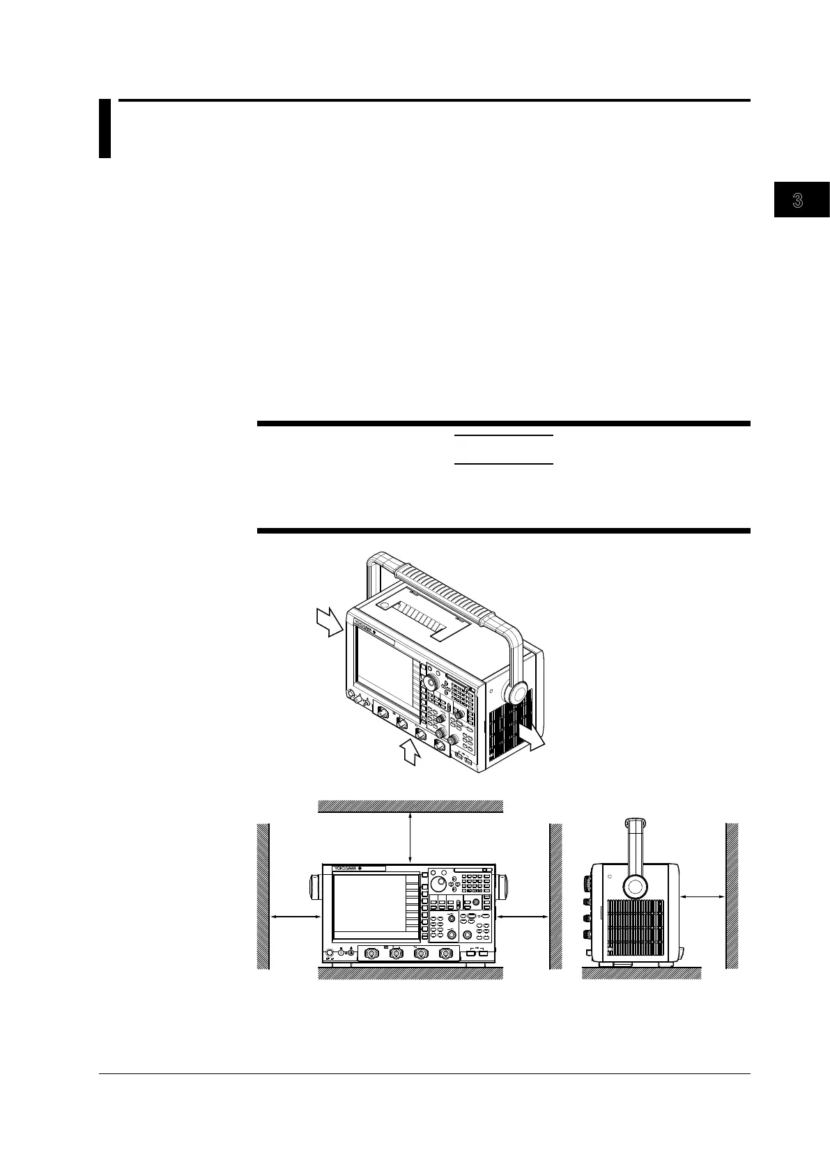
Well-Ventilated Location
Inlet holes are located on the top and bottom of the instrument. There are also exhaust
holes on the right side. To prevent internal overheating, allow for enough space around
the instrument (see the figure below) and do not block the inlet and exhaust holes.
CAUTION
If the inlets on the left and bottom side of the instrument, and exhaust holes on the
right side are blocked, the temperature of the instrument will rise, and can result in
damage.
ESC
RESET
SET
M
k
m
u
n
p
D
E
F
X
A
B
C
7
8
9
4
5
6
1
2
3
0
BS
CLEAR
EXP
MENU
PRINT
FILE
UTILITY
FILE
SYSTEM
SHIFT
SETUP
HELP
HISTORY
CLEAR
HISTORY
ACQ
COUNT/ACTION
ZO OM
DISP
1
DISP
2
ZOOM
1
ZOOM
MAG
ACQUIRE/HORIZONTAL
ACQ
START/STOP
SAMPLING/
LENGTH
POSITION/
DELAY
T/DIV
TRIGGE R
EDGE/
STATE
ENHANCED
WIDTH
EVENT
INTERVAL
SOURC E
INTENSITY
ACCUM
FORM
ACCUM
AN ALYS IS/
XY
WINDOW
1
WINDOW
2
CURS OR
TELECO M
TEST
PARAM
VE RTI CAL
CH
1
M
1
CH
2
CH
3
CH
4
M
2
M
3
M
4
POSITION
TRIG'D
TRIG MODE/
HOLD OFF
PUSH
FINE
PUSH
FINE
SCALE
SNAP
CLE AR
SNAP
POWER
COMP
CH
2
3
4
1
M /20 pF
150
Vrms
CATI
50
5
Vrms,10Vpk
LEVEL/
COUPLING
DL9240L
10GS /s
1.5 GHz
DIG ITAL OS CI LLO SCO PE
CH
CH
1
CH
DIS PLAY
CLEAR
10 cm
or more
10 cm
or more
10 cm or more
5 cm
or more
ESC
RESE T
SET
M
k
m
u
n
p
D E F X
A
B
C
7
8 9
4
5
6
1
2
3
0
BS
CLEAR
EXP
MENU
PRINT
FILE UTILI TY
FILE
SYSTEM
SHIFT
SETUP
HELP
HISTORY
CLEAR
HISTORY
ACQ
COUNT/ACTION
ZOOM
DISP 1
DISP 2
ZOOM 1
ZOOM
2
MAG
ACQUIRE/HORIZ ONTAL
ACQ
START/STOP
SAMPLING/
LENGTH
POSITION/
DELAY
T/DIV
TRIGGER
EDGE/
STATE
ENHANCED
WIDTH
EVENT
INTERVAL
SOURCE
DISPLAY
INTENSITY
ACCUM
CLEAR
FORM
ACCUM
ANALYSIS/
XY
WINDOW 1
WINDOW 2
MEAS URE
CURSOR
TELEC OM TE ST
PARAM
VERTICAL
CH
1
M 1
CH 2
CH 3
CH 4
M 2
M 3
M 4
POSITION
TRIG'D
TRIG MODE/
HOLD OFF
PUSH
FINE
PUSH
FINE
SCALE
SNAP
CLEAR
SNAP
POWER
COMP
CH 1 CH 2 CH 3 CH 4
1
M /20 pF 150
Vrms
CATI 50 5
Vrms,10Vpk
LEVEL/
COUPLING
DL9240L
10GS/s
1.5GHz
DIGITAL OSCILLOSCOPE
Including the spaces shown in the drawing above, allow for plenty of space to connect
the cables and to open and close the cover of the built-in printer.

 Loading...


