Triggering
3
2
1
4
5
6
7
8
9
10
11
12
13
14
15
16
17
18
19
App
Index
6-47
IM 701310-01E
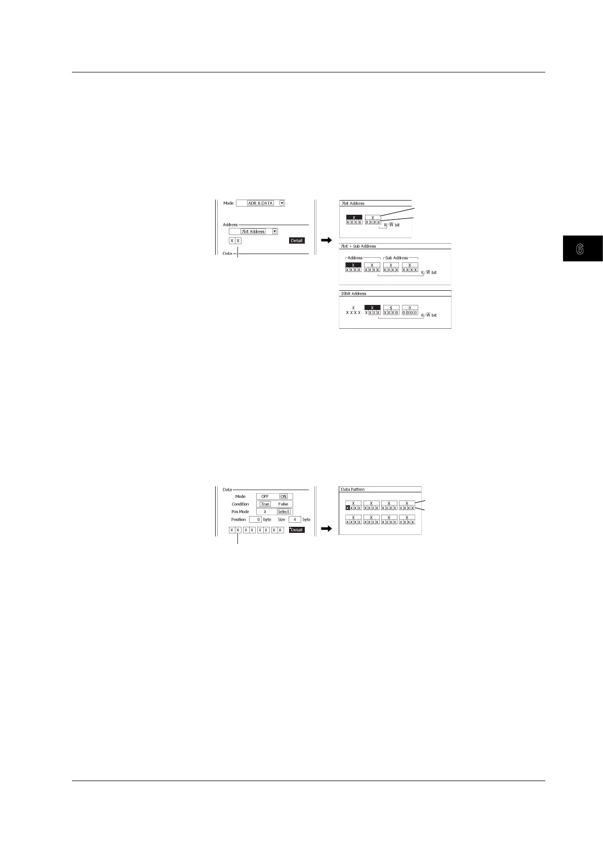
When the Mode Is ADR & DATA
• Setting the Address Trigger Condition
5.
Use the rotary knob and SET to select the address type from 7bit Address to
10bit Address.
6.
Use the rotary knob and SET to set the address pattern to compare with.
You can also set the address pattern by selecting Detail to open a dialog box and use the
rotary knob and SET and soft keys. When you are done setting the address pattern, press
ESC
to return to the previous screen.
Hexadecimal
Binary
Set the address pattern
(hexadecimal)
• Setting the Data Trigger Condition
7.
Use the rotary knob and SET to set the mode to ON or OFF.
Select ON to enable the trigger condition. Select OFF to disable the trigger condition.
If you select OFF, proceed to step 10 on page 6-49.
8.
Use the rotary knob and SET to set the condition to True or False, set Pos Mode
to X or Select, and set the position and size.
9.
Use the rotary knob and SET to set the data pattern to compare with.
You can also set the data pattern by selecting Detail to open a dialog box and use the rotary
knob and SET and soft keys. When you are done setting the data pattern, press
ESC
to
return to the previous screen.
Hexadecimal
Binary
Set the data pattern
(hexadecimal)
Proceed to step 10 on page 6-49.
6.15 Triggering on an I
2
C Bus Signal
 Loading...


