Triggering
3
2
1
4
5
6
7
8
9
10
11
12
13
14
15
16
17
18
19
App
Index
6-65
IM 701310-01E
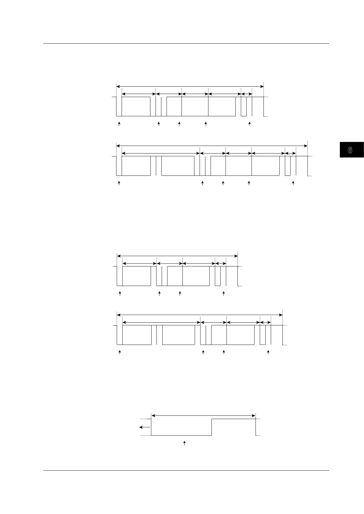
Frame Format and Trigger Point
The following figure shows the frame and trigger point of each frame.
Data Frame
1 11 1 1 1 4 158N (0≤N≤8) 1 1 1
ID 28-18
Arbitration Field
Control Field Data Field CRC Field
ACK
Data Frame
DLC
3-0
CRC
Sequence
Data
7
EOF
(1) (2) (3) (4) (5)
Positions (1) to (5) above are trigger points for the following conditions.
(1) Mode: SOF
(2) Mode: ID X*, Frame (RTR): Don’t care, ACK: Don’t care
(3) Mode: ID X*, Frame (RTR): Data, Data Field: Don’t care, ACK: Don’t care
(4) Mode: ID X*, Frame (RTR): Data, Data Field: Not Don’t care, ACK: Don’t care
(5) ACK: Not Don’t care
* ID X: ID Std/Data, ID Ext/Data, or ID/Data OR
• Standard format
1 11 1 1 1 4 8N (0≤N≤8) 15 1 1 1 71 1 18
ID 28-18
ACK
Data Frame
ID 17-0
DLC
3-0
CRC
Sequence
EOF
Data
(1) (2) (3) (4) (5)
• Extended format
Arbitration Field
Control Field Data Field CRC Field
Recessive
Dominant
Recessive
Dominant
SOF SOF
SRR
RTR
IDE IDE
RB0
ACK Boundary
ACK slot
CRC Boundary
ACK Boundary
ACK Slot
CRC Boundary
RTR
RB0
RB1
Remote Frame
1 11 1 1 1 4 15 1 1 1
ID 28-18
Arbitration Field
Control Field CRC Field
ACK
Remote Frame
DLC
3-0
CRC
Sequence
7
EOF
(1)’ (2)’ (3)’ (4)’
• Standard format
1 11 1 1 1 4 15 1 1 1 71 1 18
ID 28-18
ACK
Remote Frame
ID 17-0
DLC
3-0
CRC
Sequence
EOF
(1)’ (2)’ (3)’ (4)’
• Extended format
Arbitration Field
Control Field CRC Field
Recessive
Dominant
Recessive
Dominant
SOF
RTR
IDE
RB0
ACK Boundary
ACK Slot
CRC Boundary
SOF
SRR
IDE
RTR
RB0
RB1
ACK Boundary
ACK Slot
CRC Boundary
Positions (1)’ to (5)’ above are trigger points for the following conditions.
(1)’ Mode: SOF
(2)’ Mode: ID X*, Frame(RTR): Don’t care, ACK: Don’t care
(3)’ Mode: ID X*, Frame(RTR): Remote, ACK: Don’t care
(4)’ ACK: Not Don’t care
* ID X: ID Std/Data, ID Ext/Data, or ID/Data OR
Error Frame
Error Frame
Data Frame or
Remote Rrame
Error Flag Error Boundary
86 ≤ Error Flag ≤ 12
Recessive
Dominant
If the mode is set to Error Frame, the
trigger point is the 6th error flag bit.
6.16 Triggering on a CAN Bus Signal
 Loading...


