2-5
IM 04P01B01-01E
Before Using the Recorder
2
• To minimize noise caused by electromagnetic induction, twist the measurement circuit
wires at short, equal intervals.
• Make sure to earth ground the protective ground terminal through minimum
resistance.
When using internal reference junction compensation on the thermocouple
input, take measures to stabilize the temperature at the input terminal.
• Always use the terminal cover.
• Do not use thick wires which may cause large heat dissipation (cross sectional area of
0.5 mm
2
or less recommended).
• Make sure that the ambient temperature remains reasonably stable. Large
temperatureuctuationscanoccurifanearbyfanturnsONorOFF.
Connecting the input wires in parallel with other devices can cause signal
degradation, affecting all connected devices.
If you need to make a parallel connection, then
• Turn the burnout detection function OFF.
• Ground the instruments to the same point.
• Do not turn ON or OFF another instrument during operation. This can have adverse
eectsontheotherinstruments.
• RTDs cannot be wired in parallel.
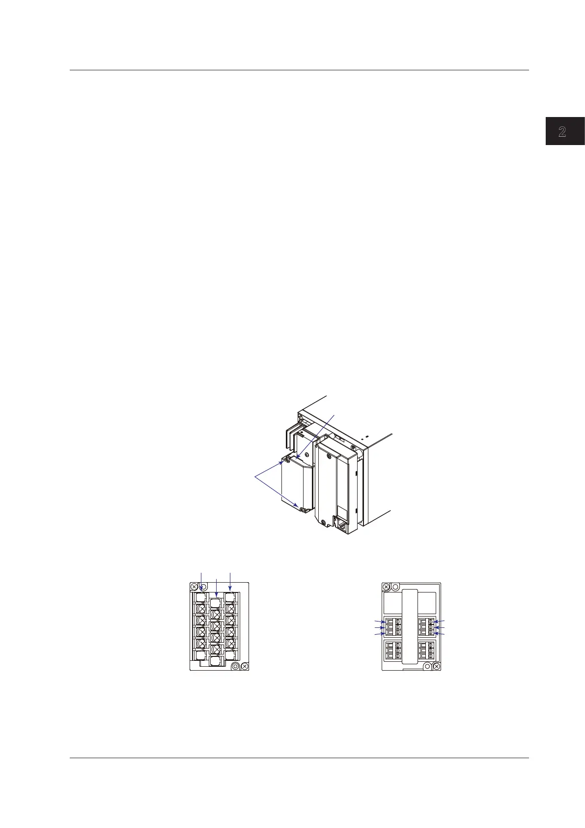
Arrangement of the Measuring Input Terminals
A terminal cover is screwed in place on the measuring input terminal block on the rear
panel. A label indicating the terminal arrangement is affixed to the cover.
Measuring input terminal block
Terminal cover
attachment screws
Pen Model
+/A
–/B
b
–/B
Channel 1
Channel 2
Channel 3
Channel 4
Channel 2
Channel 4
+/A
–/B
b
Clamped input terminal
2.3 Input Signal Wiring
 Loading...


