2-7
IM 04P01B01-01E
Before Using the Recorder
2
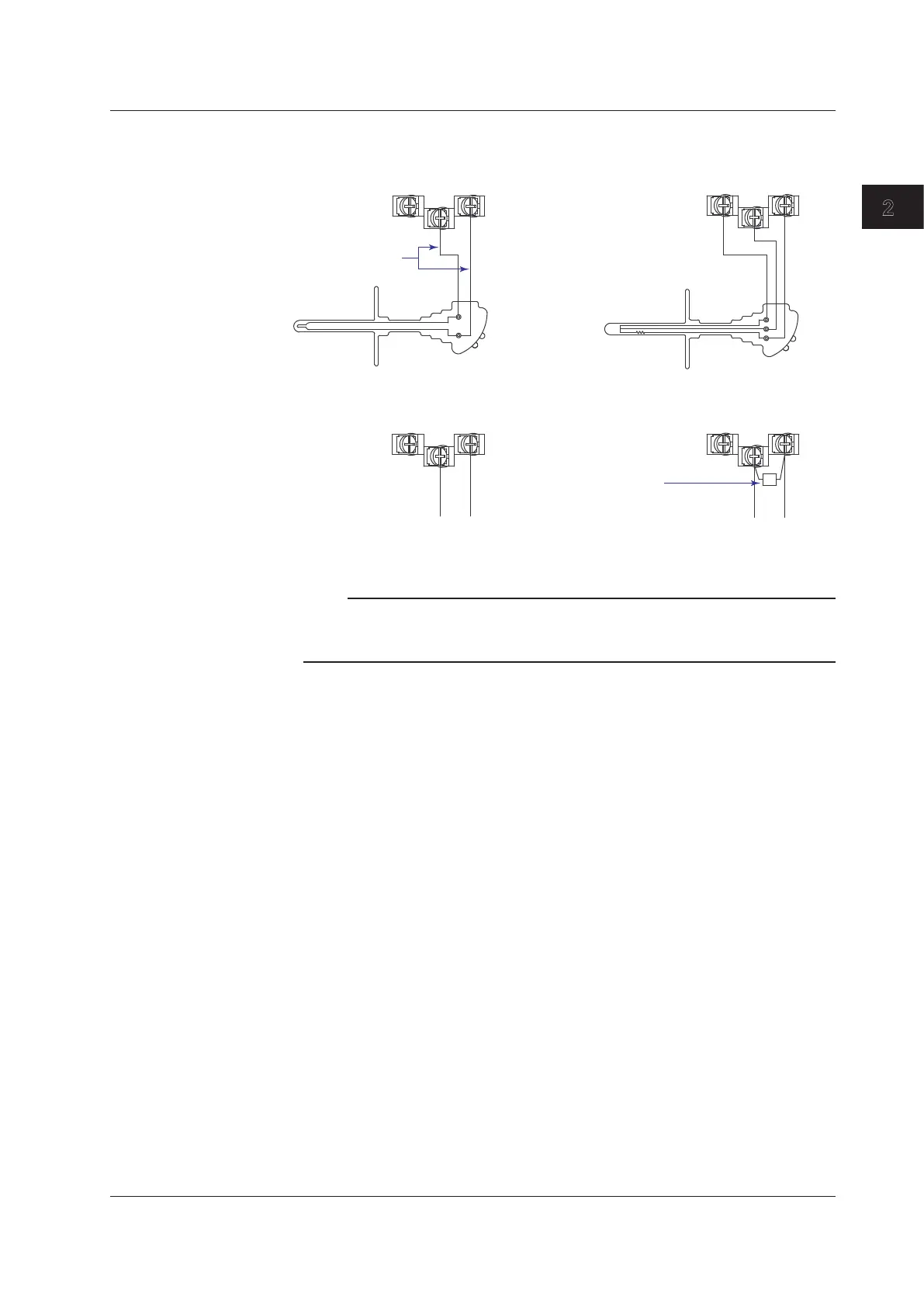
Measuring Input Wiring
–
–
DC voltage
1-5V
ON/OFF
Extension leadwire
DC current
Shunt resistor
–/Bb +/A –/Bb +/A
–/Bb +/A –/Bb +/A
+ +
Thermocouple input Resistance temperature detector input
DC voltage input, 1-5V input,
and ON/OFF input
DC current input
Leadwire resistance:
10 Ω max./wire. The resistance
of the three wires should be
equal.
Example: For a 4 to 20 mA
input, a shunt resistor of
250 Ω ± 0.1% can be used to
convert to 1-5V input.
A
B
b
Note
RTD input terminals A and B on the dot model are isolated on each channel. Terminal b is
shorted internally across all channels. However, for 3 legs isolated RTDs (/N2 option), input b is
also isolated for each channel.
2.3 Input Signal Wiring
 Loading...


