ADVANCED
PITCH2
1
LINiST
LVL
100
ADVANCED
PITCH2
l3
LI
N
1
ST
LVL
80
Helpful Hint:
The master volume setting made here can
be
set indepen-
dently and stored for each Patch as part of the
data
included
in
the Patch.
See
page
15
for more on storing operations.
Editing
Effects
The Patches in the user memory of the
9030
can be edited
and stored
to
any Patch number.
1.
Select the Patch to be edited in the Play mode.
2.
Enter the Edit mode by pressing the
EDIT
c
/
>
keys.
The Patches of the
9030
consist of nine different types of
effect modules, including a compressor group and a distor-
tion
group. (Up
to
seven effect modules can
be
used at the
same
time.) In the edit mode, each effect module
is
called up
to the display individually and the parameters of the module
can
be
set.
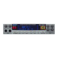
For example, when you enter the Edit mode from the Play
mode by pressing the EDIT
c
key, the display shown below
appears. This display is for editing the REV (reverb) effect
module. The effect indicator "REV" lights up in
red,
indicat-
ing that the reverb module parameters
can
currently be
edited.
TYP
RvT
PDI
COL
MIX
Rv2 2.4
60
5
40
Note:
The
FL
display shown above is only an example. The actual
values will differ depending on the Patch selected in the Play
mode.
If you enter the Edit mode from the Play mode by pressing
the EDIT
>
key, the
FL
display will show the
COMP
(com-
pressor group) effect module for editing. In either
case,
pressing the EDIT
<
key or EDIT
>
key several times toward
the same direction returns operation
to
the Play mode.
Helpful Hint:
It may
be
easy
to
think of the operation
as
circulating around
the Play mode (as shown
in
the chart below) when selecting
effect modules with the EDIT
c
/
>
keys.
3.
Change parameter values by rotating the appropriate
Data Entry Control.
Data Entry Controls
1
-
4
are used in order to change the val-
ues in the Edit mode.
Try
rotating Data Entry Control
4
to
the left then
to
the right. The value at the bottom right of the
display
((5)
in the
FL
display chart on the next page) changes
and the sound will
also
change. (In this example, the level of
the reverb changes.)
Circulation of the effect modules and the play mode
Edit
mode
i
r
1
I
Play
mode
I
I