VES1724-56 User’s Guide 26
CHAPTER 3
Hardware Overview
This chapter describes the front panel and rear panel of the Switch and shows you how to make the
hardware connections.
To protect yourself from the Switch’s high operating temperatures, wear
protective gloves before you touch the Switch.
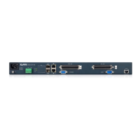
3.1 Front Panel
The following figure shows the front panel of the Switch.
Figure 7 Front Panel
The following table describes the port labels on the front panel.
3.1.1 Power Connector
Note: Make sure you are using the correct power source as shown on the panel.
Table 1 Front Panel Connections
LABEL DESCRIPTION
Power
Connection
Connect an appropriate power supply to one and only one of the ports.
Two Dual
Personality
Interfaces (25,
26)
Each interface has one 1000 Base-T copper RJ-45 port and one mini-GBIC slot, with one port
active at a time.
• 100/1000 Mbps RJ-45 GbE Ports:
Connect these Gigabit Ethernet ports to high-bandwidth backbone network Ethernet
switches.
•Mini-GBIC Slots:
Use mini-GBIC transceivers in these slots for fiber-optic or copper connections to
backbone Ethernet switches.
POTS LINE This Telco-50 port connect to the central office or a PBX .
CONSOLE The console port is for local configuration of the Switch.
VDSL LINE This Telco-50 port connect to the user (subscriber) VDSL equipment.
ALARM This port is for alarm.
MGMT Connect to a computer using an RJ-45 Ethernet cable for local configuration of the Switch.
 Loading...