Disassembly/Assembly
Guidelines
IRB 6400
Page 7 - 15
Axis 4 Guidelines
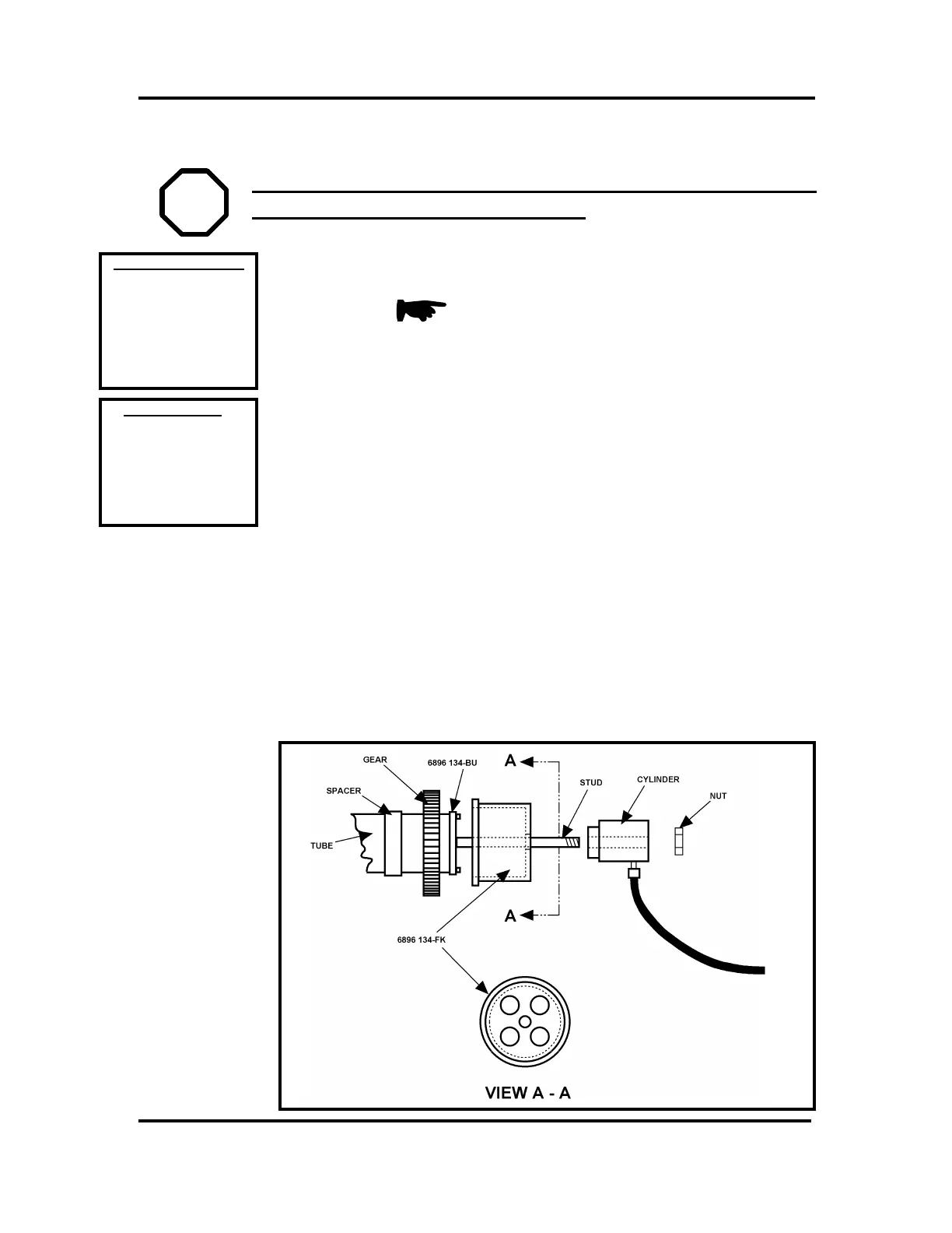
FINAL GEAR (U41) Installation
WARNING! BE SURE ELECTRICAL DISCONNECT SWITCH IS
OFF AND LOCKED IN OFF POSITION!
NOTE: Installation of final gear (U41)
requires several tools and careful assembly
procedures.
1. HEAT FINAL GEAR (U41) TO 350°F (160°C) USING AN INDUCTION
HEATER OR OVEN.
2. MOUNT TOOL ABB # 6896 134-BU ONTO END OF TUBE SHAFT
(U19).
3. BE SURE THAT SPACER (U42) IS POSITIONED IN PLACE BEHIND
FINAL GEAR (U41).
4. FOLLOWING STEPS MUST BE COMPLETED WHILE FINAL GEAR IS
STILL HOT:
a. Mount final gear (U41) onto tube shaft (U19) and quickly place
against spacer.
b. Mount tool ABB # 6896 134-FK over stud and against gear.
c. Mount hydraulic cylinder NIKE # I-CH 612 with regulator valve
NIKE # I-VRF31 over stud and screw on nut.
E
E
REFERENCE DRAWINGS
Exploded View:
“U” (pg 7-22, 12-4)
Assemblies:
3HAA 0001-AP ( pg 13-15)
3HAA 0001-CS ( pg 13-14)
3HAB 4163-2 ( pg 13-23)
3HAA 0001-AAS ( pg 14-A)
3HAB 4254-2 ( pg 14-J)
Hand Tools
REQUIRED TOOLS
ABB #6896 134-BU
SKF #234 063
ABB #6396 134-FK
NIKE #1-CH 612
NIKE #1-VRF 31
NIKE #AMT 150
Heating Oven

 Loading...


