Disassembly/Assembly
Guidelines
IRB 6400
Page 2 - 7
Safety
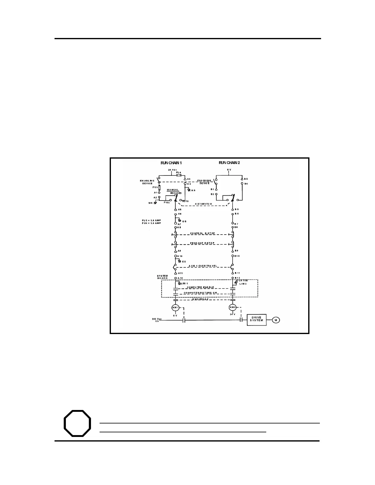
SAFETY CONTROL CHAIN OF OPERATION
The safety control order of operation is based on dual electrical safety circuits
(Run Chains) which interact with the robot computer and enable the MOTORS
ON mode.
The electrical safety circuits consist of several switches connected in series so
that ALL of them must be closed before the robot can be set to MOTORS ON
mode. MOTORS ON mode means that power is supplied to the motors.
The electrical safety chains are continuously monitored and the robot reverts
to the MOTORS OFF mode when a fault is detected by the computer. MO-
TORS OFF mode means that drive power is removed from the robot’s motors
and the brakes are applied.
The status of the switches are indicated by the LEDs on the front of the System
board (DSQC 256A) in the Control Cabinet.
If any contact in the safety chain of operation is open, the robot always reverts
to the MOTORS OFF mode.
After a stop, the switch must be reset at the specific unit which caused the stop .
After reset, the robot can be started again.
WARNING! THE SAFETY CHAINS MUST NEVER BE BYPASSED,
MODIFIED OR CHANGED IN ANY OTHER WAY!.
E
E

 Loading...


