Disassembly/Assembly
Guidelines
IRB 6400
Page 6 - 1
Axes 2 & 3 Guidelines
MOTOR (S71) Removal
NOTE: The following guideline is for axis 3 motor removal (right side
motor). Axis 2 motor (left side motor) removal procedure is identical
unless specifically noted.
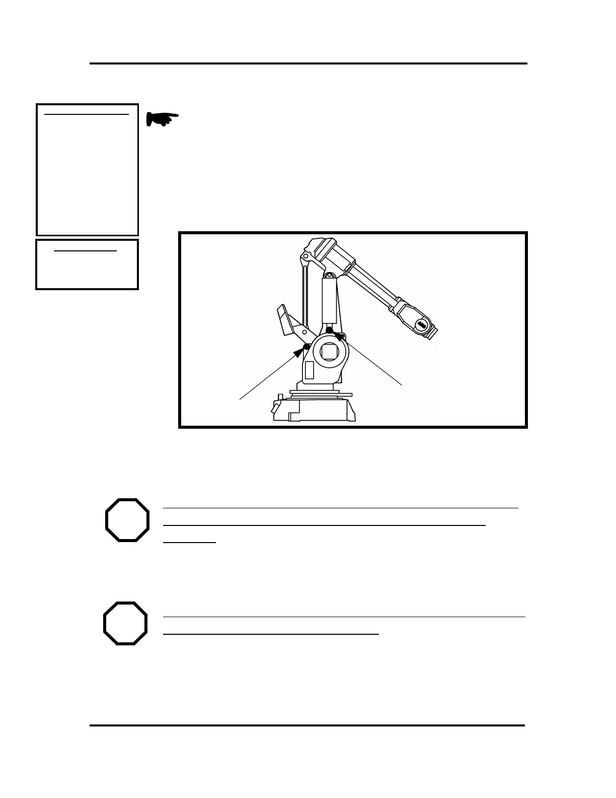
1. Position the robot as shown below.
2. Axis 2 motor (S71) removal (left side motor.)
a. Position robot so lower arm (L17) can be locked from moving with
support bars. See Figure below.
WARNING! BE SURE THAT THE AXIS YOU ARE REMOVING
THE MOTOR FROM IS MECHANICALLY LOCKED FROM
MOVING!
3. TURN ELECTRICAL DISCONNECT SWITCH OFF AND LOCK IT IN
THE OFF POSITION.
WARNING! BE SURE ELECTRICAL DISCONNECT SWITCH IS
OFF AND LOCKED IN OFF POSITION!
4. DISCONNECT CABLES (S66) FROM AXIS MOTOR (S71):
a. Axis 3 connectors are R3.MP3 & R3.FB3.
b. Axis 2 connectors are R3.MP2 & R3.FB2.
REFERENCE DRAWINGS
Exploded View:
“S” (pg 6-23, 12-2)
Assemblies:
3HAA 0001-EP (pg 13-10)
Hand Tools
Small 3-Jaw Puller
Strap Wrench
M10 x 150 Screw
REQUIRED TOOLS
3HAA 0001-RB (pg 13-6)
3HAA 0001-RB (pg 13-7)
3HAA 0001-RB (pg 13-4)
3HAB 4162-2 (pg 13-9)
3HAB 4162-2 (pg 13-8)
3HAB 4163-2 (pg 13-23)
3HAB 4167-2 (pg 13-11)
E
E
E
E
3HAA 0001-AAS (pg 14-A)
3HAA 0001-AAO (pg 14-E)
3HAB 4252-2 (pg 14-I)
BAR
SCREWS (EACH SIDE)

 Loading...


