Disassembly/Assembly
Guidelines
IRB 6400
Page 7 - 17
Axis 4 Guidelines
TUBE SHAFT (U19) Removal
NOTE: Removal of tube shaft (U19) requires
several tools and careful disassembly proce-
dures.
1. TURN MAIN ELECTRICAL DISCONNECT SWITCH OFF AND LOCK IT
IN THE OFF POSITION.
WARNING! BE SURE ELECTRICAL DISCONNECT SWITCH IS
OFF AND LOCKED IN OFF POSITION!
2. REMOVE UPPER CABLE (U14) as outlined in Section 10.
3. REMOVE WRIST ASSEMBLY (U10) as outlined in Section 9.
4. REMOVE FINAL GEAR (U41) as outlined on page 7 - 12.
5. REMOVE MECHANICAL STOP (U25):
a. Remove screws (U22) with washers (U24).
b. Remove axis 4 stop (U25), gasket (U27), and rubber cushion
(U26). Axis 4 may have to be turned to gain access to cushion.
c. Rotate axis 4 until stop (U13) is visible. Remove screws (U11)
and stop (U13).
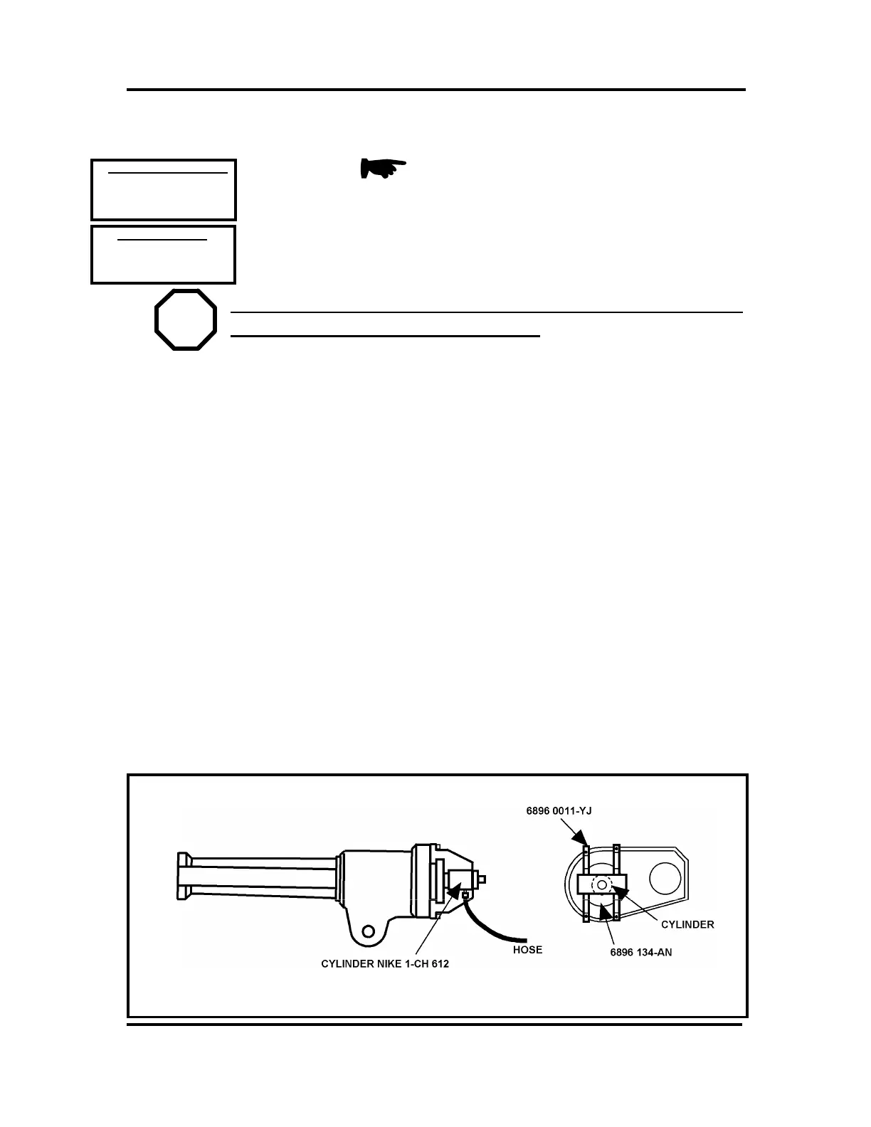
6. REMOVE TUBE SHAFT (U19):
a. Press tube shaft (U19) out with tool ABB # 6896 0011-YJ and tool
NIKE # 1-CH 612. Protect the surface at end of tube shaft.
Scratches will result in oil leakage through seal ring (U40) in
cover (U54).
b. Remove seal (U48), bearing (U46), and seal (U45).
E
E
REFERENCE DRAWINGS
Exploded View:
Assembly:
3HAA 0001-CS ( pg 13-16)
REQUIRED TOOLS
“U” (pg 7-22, 12-4)
Hand Tools
ABB #6896 0011-YJ
NIKE #I-CH 612
ABB #6896 134-AN

 Loading...


