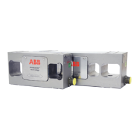
Tension Electronics PFEA113, User Manual
Table of Contents
3BSE029382R0101 Rev C viii
CONTENTS (continued)
F.11 Cable Diagram 3BSE028144D0065, Page 3/7, Rev. D......................................... F-15
F.12 Cable Diagram 3BSE028144D0065, Page 7/7, Rev. D......................................... F-16
F.13 Dimension Drawing, 3BSE006699D0003, Rev. F ................................................ F-17
F.14 Dimension Drawing, 3BSE029522D0001, Rev. B................................................ F-18
F.15 Dimension Drawing, 3BSE006699D0006, Rev. - ................................................. F-19
F.16 Dimension Drawing, 3BSE006699D0005, Rev. J ................................................. F-20
F.17 Dimension Drawing, 3BSE006699D0004, Rev. H................................................ F-21
Appendix G - PFTL 201 - Designing the Load Cell Installation
G.1 About This Appendix...............................................................................................G-1
G.2 Basic Application Considerations............................................................................G-1
G.3 Step-by-Step Guide for Designing the Load Cell Installation .................................G-2
G.4 Installation Requirements ........................................................................................G-3
G.5 Mounting Alternatives, Calculating Force and Calculating Wrap Gain..................G-4
G.5.1 Horizontal Mounting...............................................................................G-4
G.5.2 Inclined Mounting...................................................................................G-5
G.6 Force Calculation for Measurement with a Single Load Cell .................................G-6
G.6.1 The Most Common and Simple Solution ...............................................G-6
G.6.2 Force Calculation when the Web is not Centered on the Roll ................G-7
G.7 Mounting the Load Cells .........................................................................................G-8
G.7.1 Preparations ............................................................................................G-8
G.7.2 Adapter plates .........................................................................................G-8
G.7.3 Mounting.................................................................................................G-8
G.7.4 Cabling..................................................................................................G-10
G.8 Technical data load cell PFTL 201 ........................................................................G-11
G.9 Cable Diagram 3BSE028144D0065, Page 1/7, Rev. D .........................................G-13
G.10 Cable Diagram 3BSE028144D0065, Page 2/7, Rev. D.........................................G-14
G.11 Cable Diagram 3BSE028144D0065, Page 3/7, Rev. D.........................................G-15
G.12 Cable Diagram 3BSE028144D0065, Page 7/7, Rev. D.........................................G-16
G.13 Dimension Drawing, 3BSE008723, Rev. D ..........................................................G-17
G.14 Dimension Drawing, 3BSE008904, Rev. D ..........................................................G-18
G.15 Dimension Drawing, 3BSE008724, Rev. F ...........................................................G-19
G.16 Dimension Drawing, 3BSE008905, Rev. G ..........................................................G-20
G.17 Dimension Drawing, 3BSE008917, Rev. H ..........................................................G-21
G.18 Dimension Drawing, 3BSE008918, Rev. G ..........................................................G-22
Appendix H - Actual Data and Settings at Commissioning
H.1 Document the Commissioning in this Form ............................................................H-1
 Loading...
