Tension Electronics PFEA113, User Manual
Chapter 2 Installation
2-12 3BSE029382R0101 Rev C
2.8 Connecting the Load Cells
Information for connecting the load cells is given in the appendix for each load cell type, see
table below.
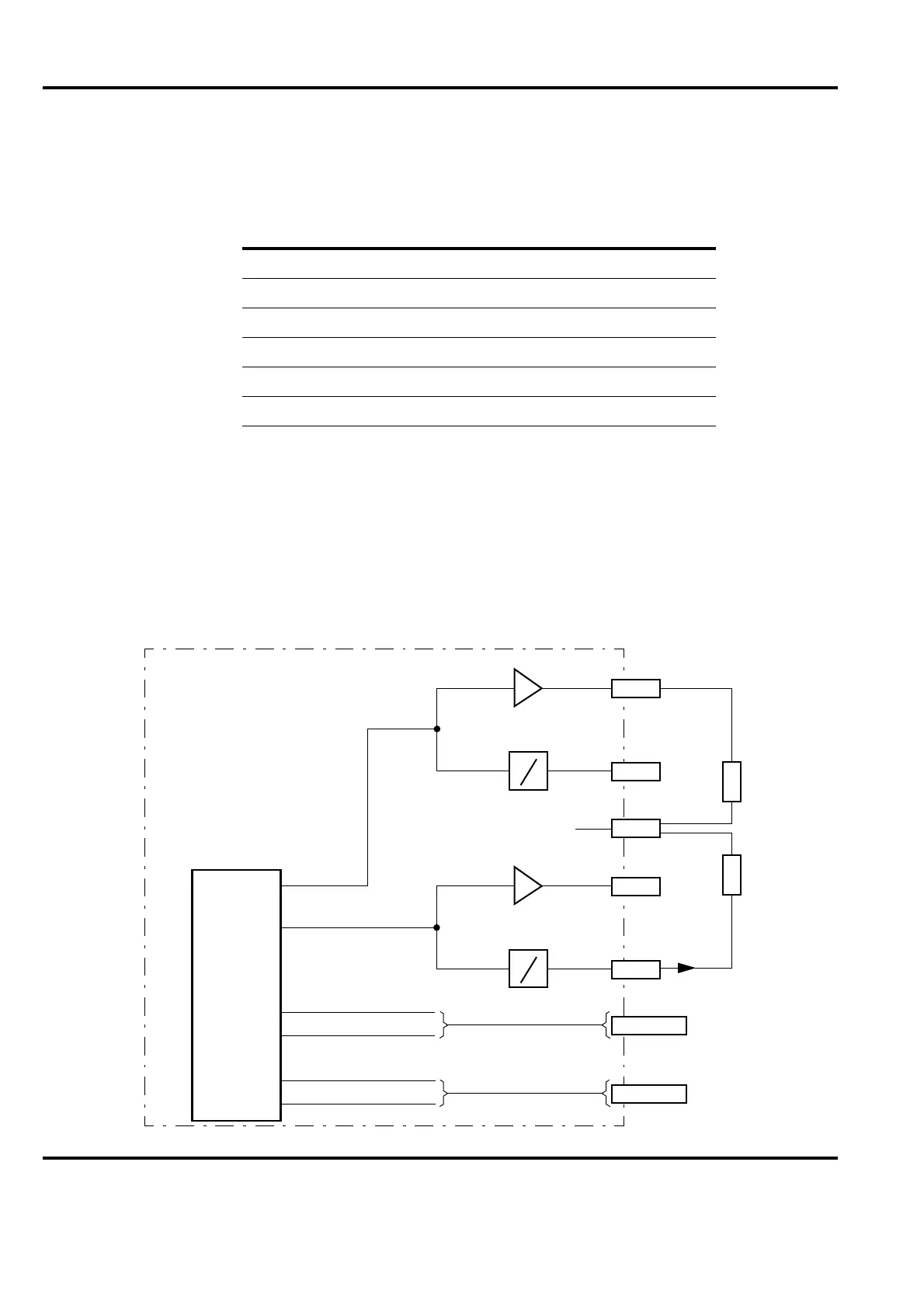
2.9 Connecting Analog Outputs (AO1-AO6)
There are six analog outputs. Each output can be set either for voltage or current. Each analog
output from the digital/analog converter is a voltage. This is split into two outputs, one of which
is converted into a current output and the other kept as voltage. This is illustrated in Figure 2-12
where for example X4:1 is the voltage output and X4:2 is the current output.
The allowed load current of the voltage output is max. 5 mA.
The allowed load resistance of the current output is max. 550 ohms.
Figure 2-12 shows AO1 connected for voltage output and AO2 for current output.
Figure 2-12. Connecting Analog Outputs
Type of load cell Cable diagrams in Appendix
PFCL 301E B
PFTL 301E C
PFRL 101 D
PFTL 101 E
PFCL 201 F
PFTL 201 G
Voltage
D/A-
converter
12
AO1
AO2
AO3
AO4
PFEA113
X4:4
U
I
R
L
X4:5
X4:3
Current
X4:1
U
I
R
L
+
–
X4:2
0 V
bits
AO5
AO6
X4:6-10
X4:11-15
See circuit diagram
for AO1 and AO2
Max. 550
output
output
Max. 5 mA
U
I
U
I