Tension Electronics PFEA113, User Manual
Chapter 2 Installation
2-6 3BSE029382R0101 Rev C
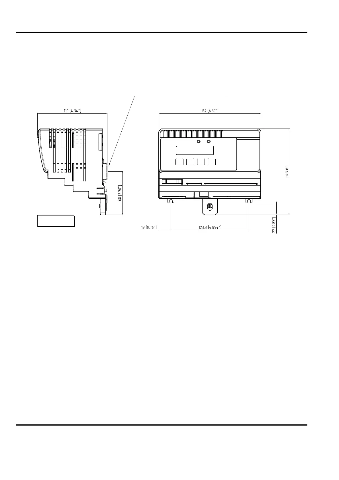
2.4.2.2 IP 20-version (Unsealed)
Figure 2-5. Installation Dimensions
Connect the cables to the terminals according to cable diagrams in Appendix (B, C, D, E, F or
G) depending on the type of load cell installed.
NOTE
Do not connect solid conductors to terminals. Do not crimp pins to stranded
cores.
Earthing
The metal bottom of PFEA113-20 connects to the metallic DIN-rail which serves as the
Tension Electronics earth connector.
This is to ensure a good earth connection both for internal logic and for the EMI immunity and
RF emission of the electronics.
The DIN-rail must have a good connection to the PE (Protective Earth) of the cabinet.
To achieve the best possible corrosion resistance, DIN-rails should be chromium plated, for
instance, yellow chromium treated. Use star washers with each screw used to fasten the DIN-
rail to the mounting plate.
To fasten the DIN-rail onto the mounting plate, the minimum screw diameter is 5 mm and the
maximum distance between screws is 100 mm.
DIN-rail 35 x 7.5 mm (EN 50022-35x7.5 or equivalent)
mm [inches]