Tension Electronics PFEA113, User Manual
Section 2.7 Connectors on the PFEA113
3BSE029382R0101 Rev C 2-11
2.7 Connectors on the PFEA113
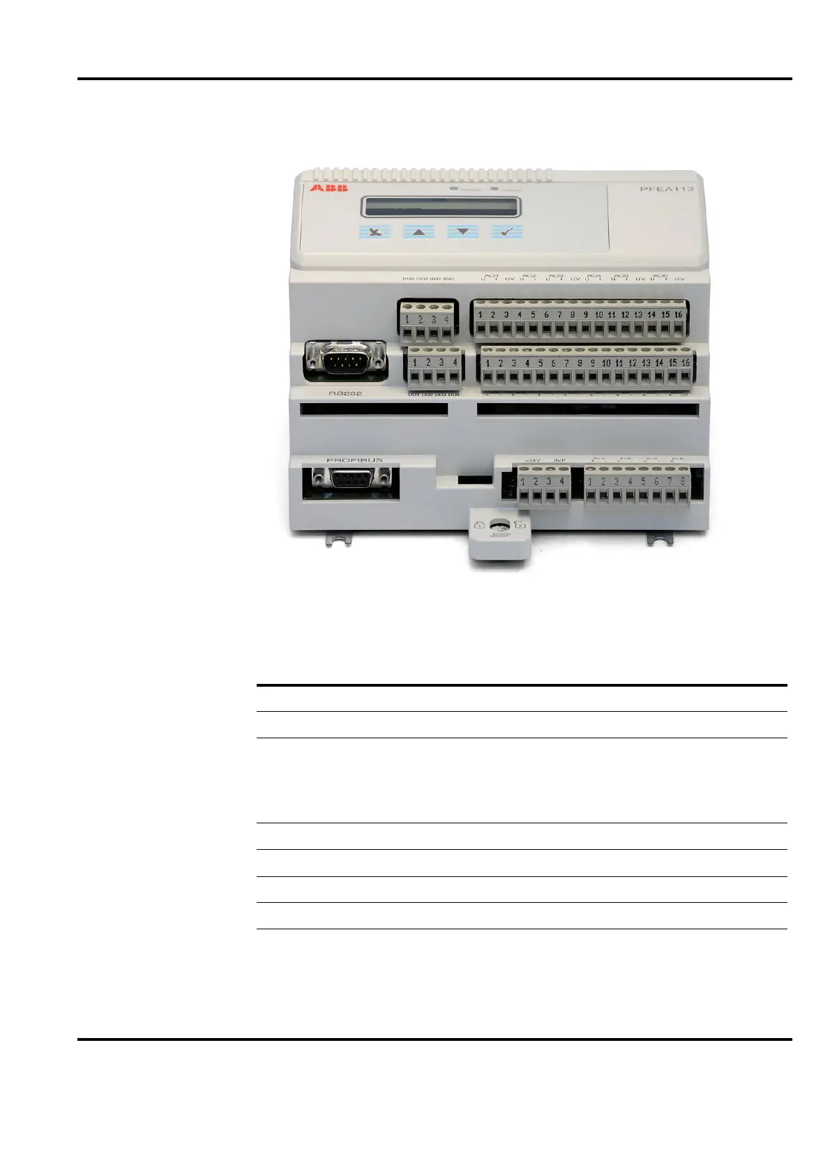
Figure 2-11. Connectors on the PFEA113
Table 2-3. Description of PFEA113 connectors
Connector number Description
X1:1-X1:4 24 V Supply connections (X1:1-X1:2), 0V (X1:3-X1:4)
X2:1-X2:8 Connectors for the wiring to the load cell excitation circuits
X3:1-X3:16 X3:1-X3:8 Connectors with signals from load cells.
X3:9-X3:12 are AI1 and AI2.
X3:13-X3:14 is DI1. X3:15-X3:16 is the Synchronization Signal
Input.
X4:1-X4:16 Analog outputs
X5:1-X5:4 Digital outputs
X6:1-X6:4 Digital out supply (1), and three 0VD
X7 PROFIBUS D-Sub connector
X8 RS232 Connector
X5:1-X5:4
X2:1-X2:8
X7
X8
X1:1-X1:4
X4:1-X4:16
X3:1-X3:16
X6:1-X6:4