Tension Electronics PFEA113, User Manual
Section 6.1 About this Chapter
3BSE029382R0101 Rev C 6-1
Chapter 6 Fault-tracing
6.1 About this Chapter
During the working life of your measurement system, events may occur that disturb it and your
process. These disturbances may appear in many different ways and the reason for the fault can
be difficult to find. However, disturbances similar in character can be grouped together and
usually they have the same or similar sources of error.
The fault-tracing instructions in this chapter will help you to quickly find and correct the most
common faults.
6.2 Safety Instructions
Read and follow the safety instructions given in Chapter 1 Introduction when tracing faults.
However, local statutory regulations, if stricter, are to take precedence.
6.3 Interchangeability
6.4 Necessary Equipment and Documentation
The following items are required to perform fault-tracing and repairs:
• Cable diagrams, see Appendix (B, C, D, E, F or G) for installed load cell type
• Service tools
• Torque wrench
• Multimeter
Unit Measures
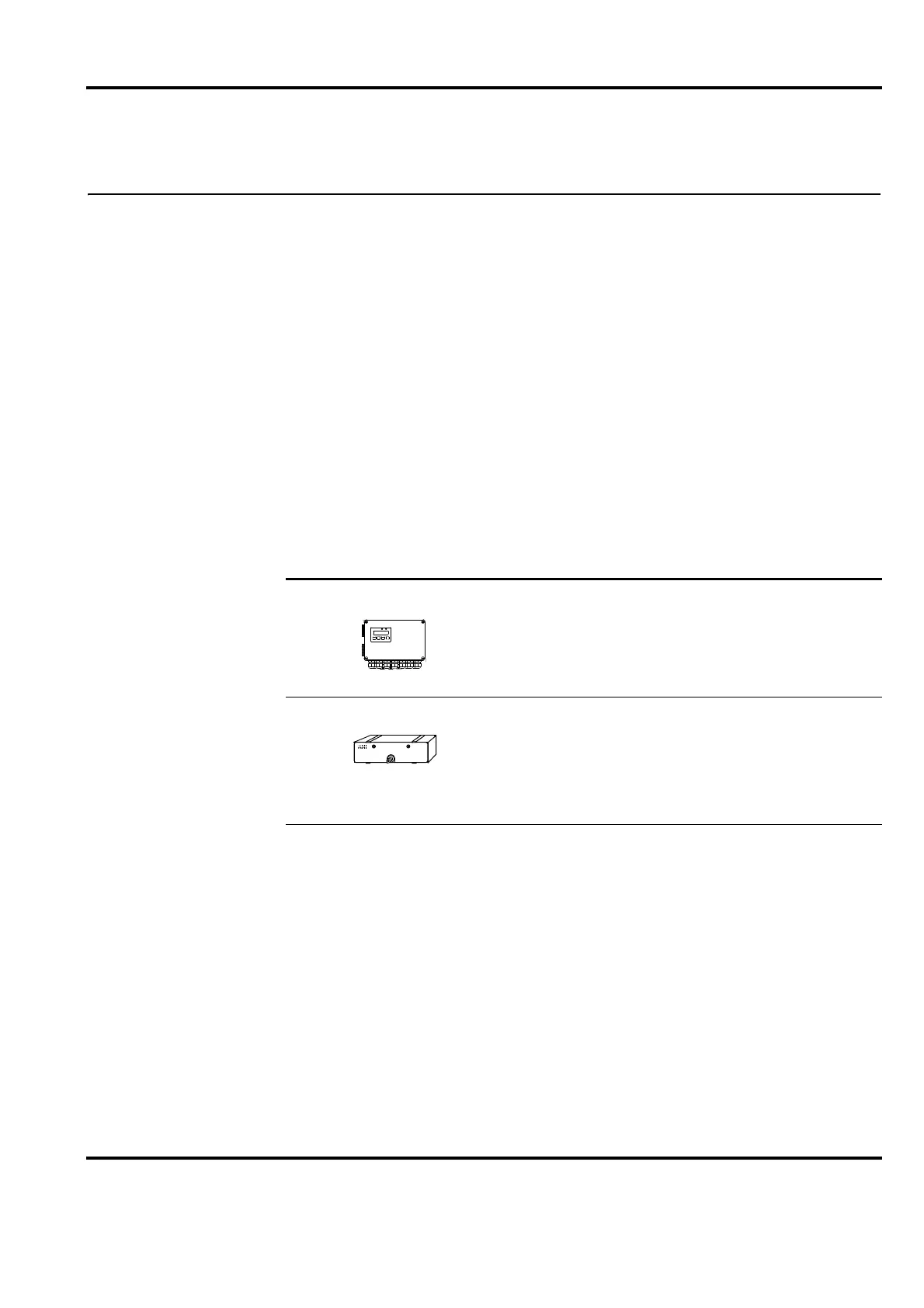
Tension Electronics The tension electronics PFEA113 is interchangeable
with a tension electronics of the same type.
A new setup is required.
Load cells The load cells are directly interchangeable
with other load cells of the same type.
Zero setting PFEA113 and resetting “Maximum
Load A”, “Maximum Load B”, “Maximum Load C” or
“Maximum Load D” are required after a load cell has
been replaced.