Technical data
Product manual 2CKA001473B5343
32
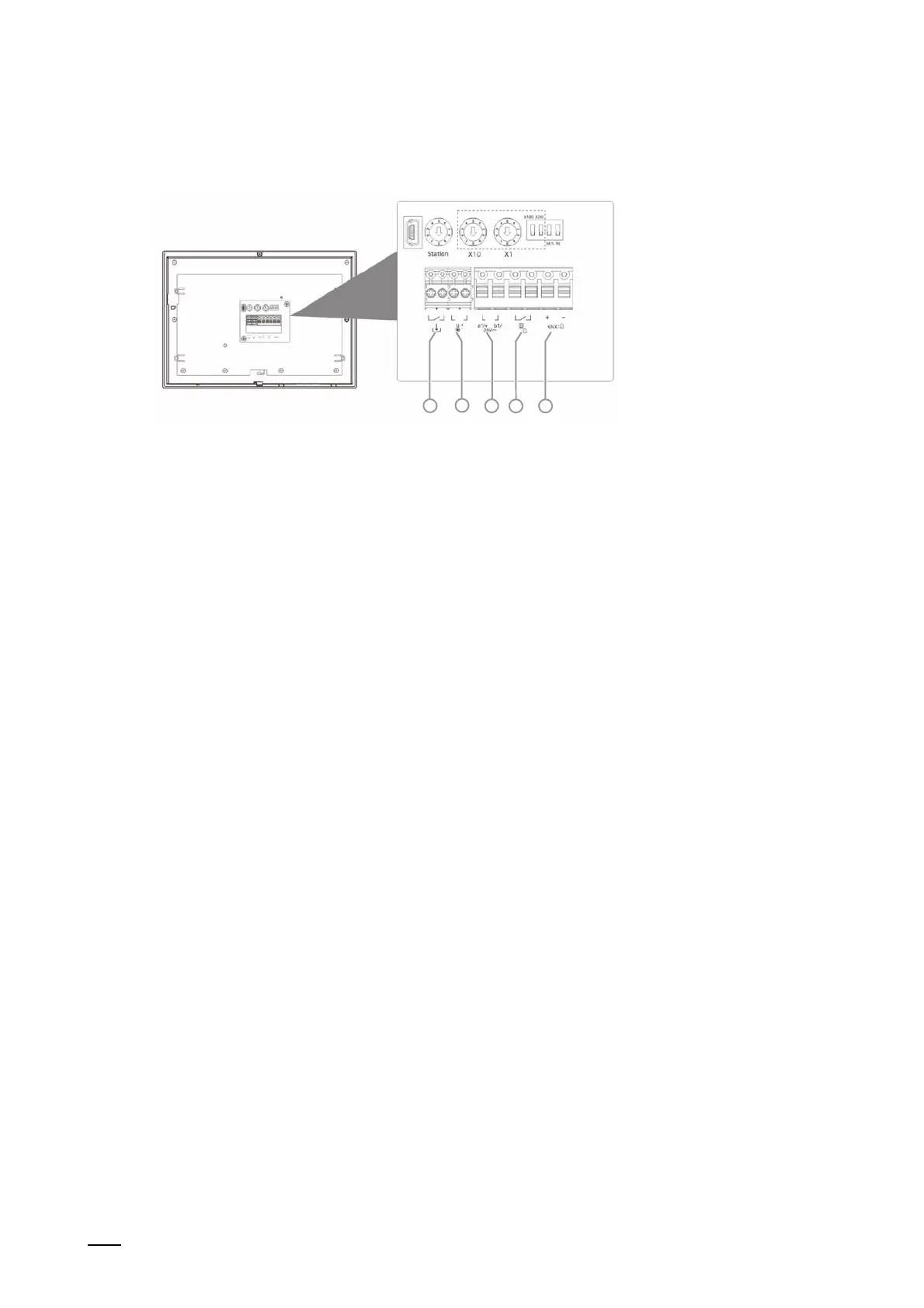
5.2 Circuit diagrams
4 2 15 3
Fig. 5: Electrical connection
Po
s.
Function
1 Connection for the ABB i-bus
®
KNX / free@home
2 Connection for the floor call button
3 Connection for the central control system or the external power supply (e.g. CP-D 24/2.5)
When using several indoor stations: connection for the internal bus.
4 Temperature sensor connection
DP4-T-1 or PT1000
5 Binary input connection
Table 4: Function of connection