ADT-HC4500 Flame/Plasma Cutting Machine CNC System
- 126 -
Appendix 2: Example of Editing Processing Graphics
In the main interface, press [F3] to enter the edit interface, and then press [F1] to create a new processing file,
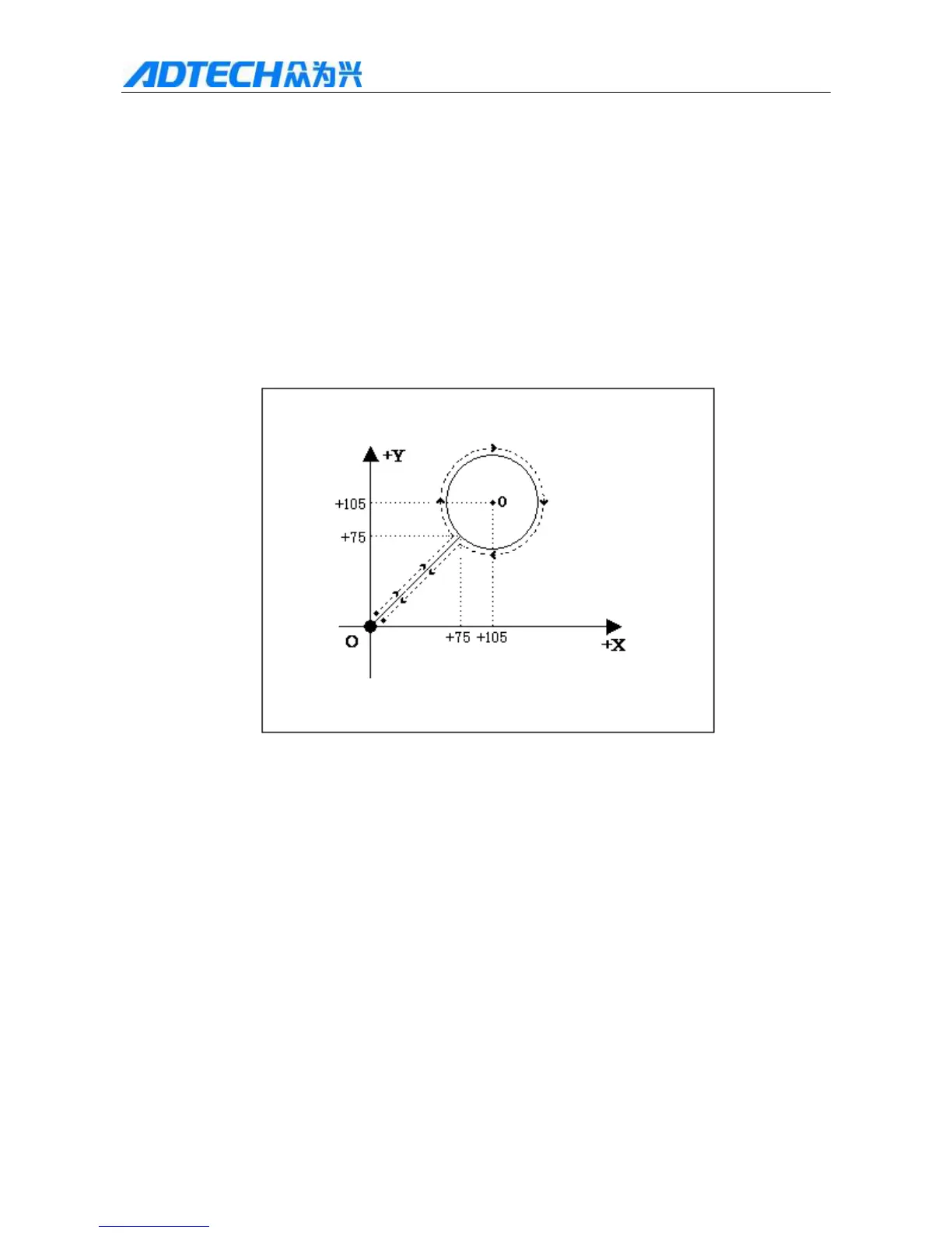
enter the file name, press [OK] to enter file edit interface. Take cutting the figure below as an example (the
dashed and arrows are the motion direction, the real line is the cutting track, and “” is the cutting start):
Remark: Absolute coordinates are not used commonly and won’t be introduced. The following example is relative
coordinates.
1. Standard circle
The graphics program follows:
Relative coordinate programming and graphics code description:
0000: G92 X0 Y0——Reference point setting;
0001: G22 L3——L indicates processing cycle setting; 3 indicates 3 cycles;
0002: G41——Left compensation
0003: M07——Preheating and perforating function. Prompt: Please set the time parameters
in [Parameter] – [Control] properly;
0004: G01 X75 Y75——Perforating lead;
0005: G02 I30 J0——Clockwise circle processing;
0006: M08——Turn off cutting oxygen valve;
0007: G00 X-75 Y-75——Space shift to the origin at top manual speed;
 Loading...