ADT-HC4500 Flame/Plasma Cutting Machine CNC System
- 50 -
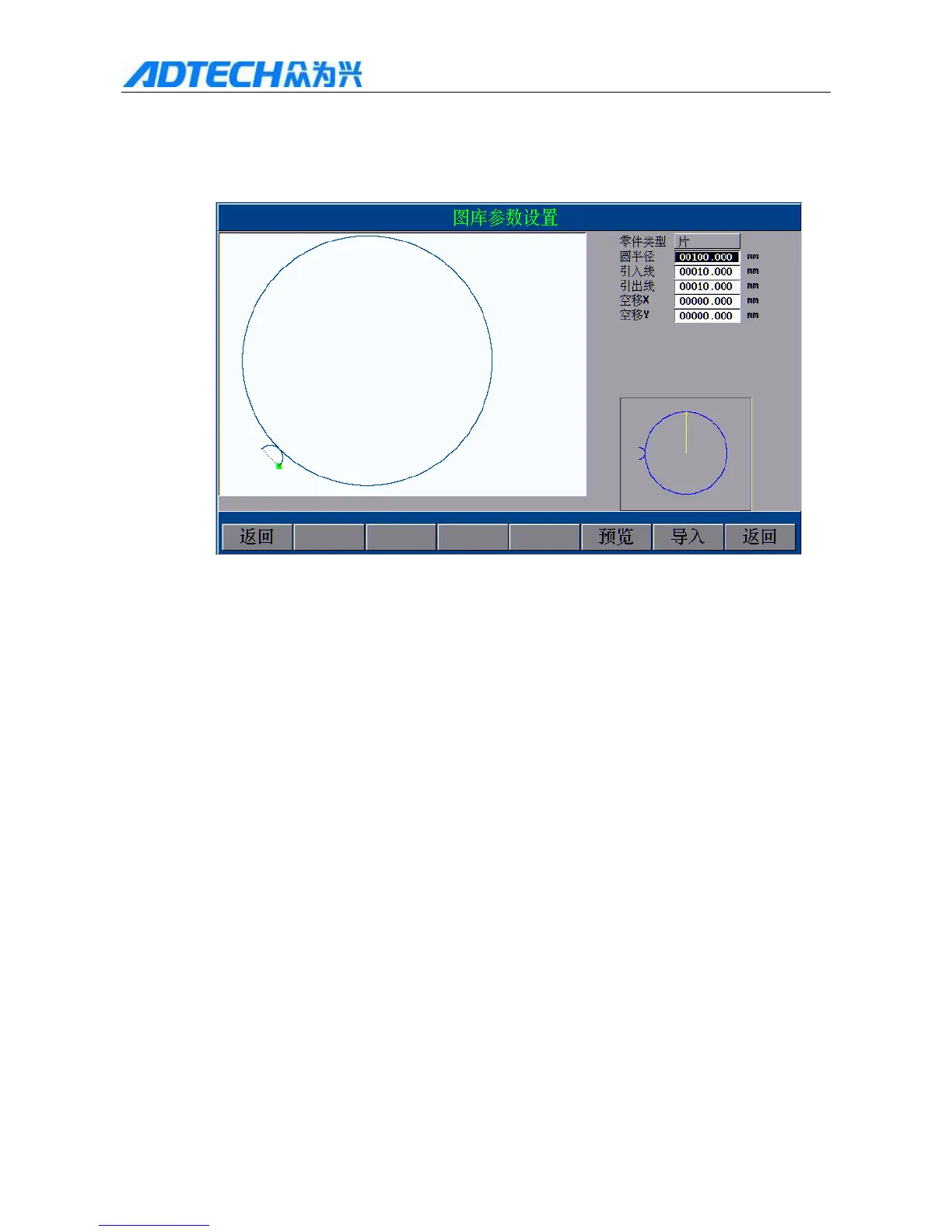
Fig. 2.1
We will take “Circle” as an example for description. Move the blue frame to the circle and press [OK] to enter the
graphics.
Graphics Library Parameters Settings
Part type: piece
Radius
Lead-in wire
Lead-out wire
X :Place shit X
Y:Place shift Y
Return / Preview / Import / Return
Fig. 2.3
By setting the parameters, the user can get different processing graphics.
Part type: Select to cut into pieces or holes; for pieces, the part inside the graphics frame is the desired workpiece;
for holes, the part outside the graphics frame is the desired workpiece.
Lead-in/out wire: Lead-in wire (arc) is the wire (arc) reserved to prevent over-burning of perforating point.
Lead-out wire (arc) is used for plasma cutting process, during which the lead-out wire (arc) will cause arc
breaking. The lead-in/out wire (arc) for holes cutting is inside the graphics, while the lead-in/out wire (arc) for
pieces cutting is outside the graphics.
Space shift wire: the run idle distance from processing start to perforating point.
 Loading...