Appendix C External Tanks 137
USG-CUS-059 Rev05MassARRAY® Nanodispenser RS1000 v2.1 User Guide
For Research Use Only. Not for use in diagnostic procedures.
3. Place the external supply tank in its final location.
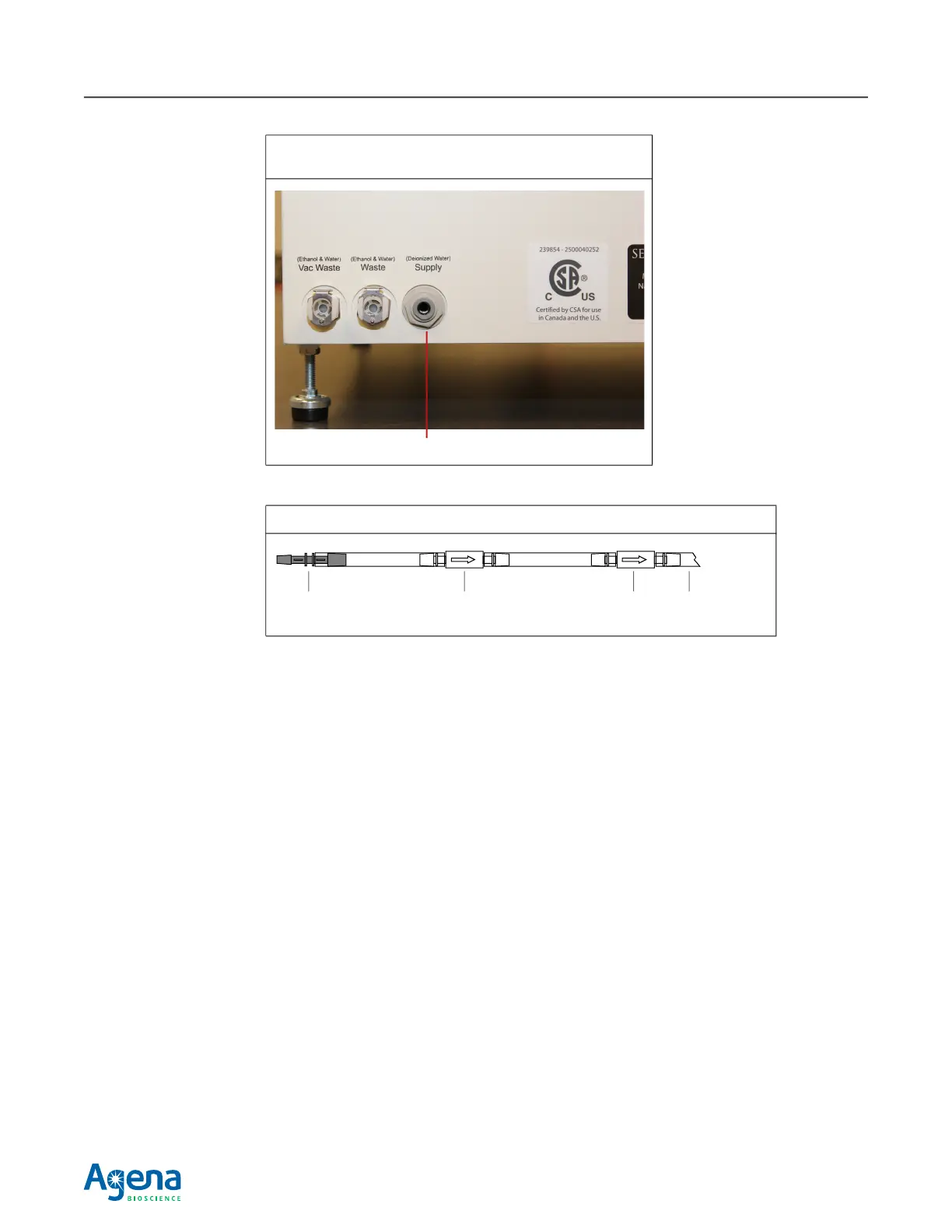
4. Insert the filter end of the supply tubing into the external supply tank.
Make sure that the end of the tubing with the metal fitting is at the bottom of the
reservoir so that air will not be drawn into the tubing. The metal fitting helps
compensate for the tendency of the tubing to float when it is empty.
5. Manually fill the internal supply tank to at least half-full (see page 99 for instructions
and Table 4.1, page 89 for valve positions).
This is necessary to prevent triggering the low fluid level sensor in the internal supply
tank. If the low fluid level sensor is triggered, the instrument will not dispense.
6. Open the main door and lift the front access panel to access the tank control valves.
See page 10 for instructions on opening the front access panel.
7. Set the supply tank valves to position "A1" (see Table 4.1, page 89).
The supply valves should remain in these positions when using an external supply
tank. It may be necessary to turn the valves to perform certain maintenance
procedures; return the valves to positions A and 1 when done.
8. Close the front access panel and the main door.
See for page 11 for instructions on closing the front access panel.
9. Fill the external supply tank with Type 1, >18.2
MΩ water.
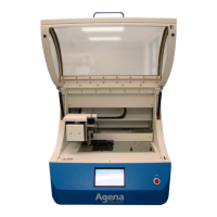
Figure C.1 Inserting Tubing into the Supply Port
The left side of the instrument is shown.
Figure C.2 Filter End of the Supply Tubing
Supply port
Inline filter Supply tubingCheck valveMetal fitting
(for weight)