EasyManuals Logo

Agilent Technologies G1313A User Manual

Agilent Technologies G1313A
292 pages
To Next Page IconTo Next Page
To Previous Page IconTo Previous Page
Page #192 background imageLoading...
Page #192 background image
192
Parts and Materials
Remote Cables
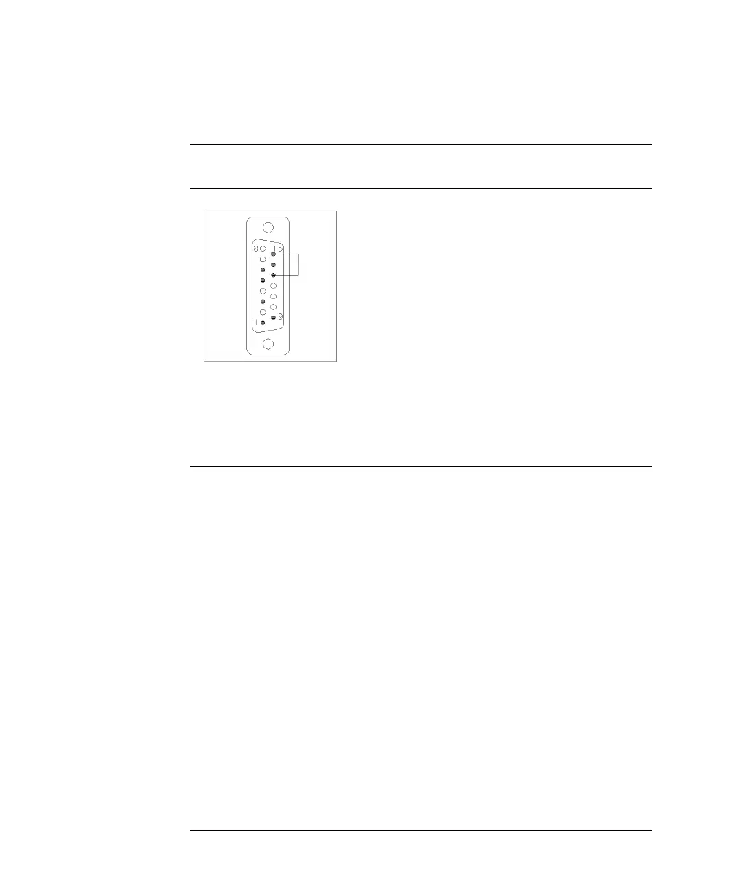
Agilent 1100 to 3396A Integrators
Agilent 1100 to 3396 Series II / 3395A Integrators
Use the cable 03394-60600 and cut pin #5 on the integrator side.
Otherwise the integrator prints START; not ready.
Connector
03394-60600
Pin
3394
Pin
Agilent 1100 Signal Name
Active
(TTL)
9 1 - White Digital
ground
NC 2 - Brown Prepare run Low
3 3 - Gray Start Low
NC 4 - Blue Shut down Low
NC 5 - Pink Not
connected
NC 6 - Yellow Power on High
5,14 7 - Red Ready High
1 8 - Green Stop Low
NC 9 - Black Start request Low
13, 15 Not
connected

Table of Contents

Questions and Answers:

Question and Answer IconNeed help?

Do you have a question about the Agilent Technologies G1313A and is the answer not in the manual?

Agilent Technologies G1313A Specifications

General IconGeneral
BrandAgilent Technologies
ModelG1313A
CategoryLaboratory Equipment
LanguageEnglish

Related product manuals