236
Theory of Operation
Setting the 8-bit Configuration Switch
Setting the 8-bit Configuration Switch
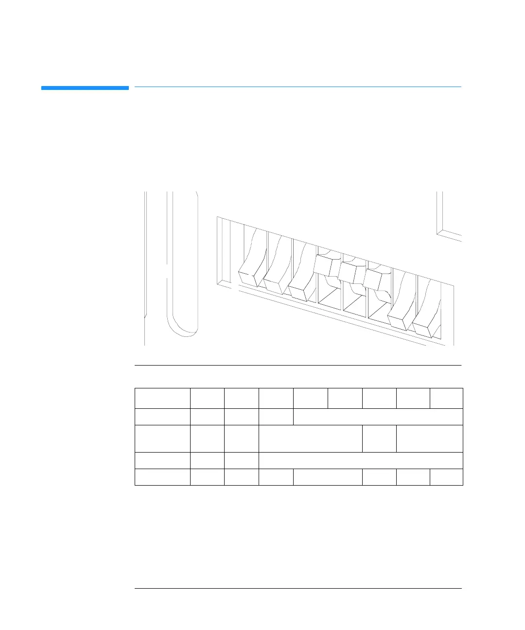
The 8-bit configuration switch is located next to the GPIB connector.
Switch settings provide configuration parameters for GPIB address, serial
communication protocol and instrument specific initialization procedures.
Figure 44 8-bit Configuration Switch
Switches 1 and 2 define which set of parameters (for example, for GPIB,
RS-232C, and so on) will be changed. Once the change has been completed,
the instrument must be powered up again in order to store the values in
the non-volatile memory.
In the non-volatile memory the parameters are kept, regardless of whether
you turn the instrument off and on again. They will be kept until the same
Table 53 8-bit Configuration Switch
Mode Select12345678
GPIB 0 0 GPIB Address
RS-232C 0 1 Baudrate Data
Bits
Parity
Reserved 1 0 Reserved
TEST/BOOT 1 1 RSVD SYS RSVD RSVD FC
factory setting is shown
for autosampler
1
8
1
0