Publication 1756-UM523F-EN-P - December 2006
132 Update Modules and Redundant Systems
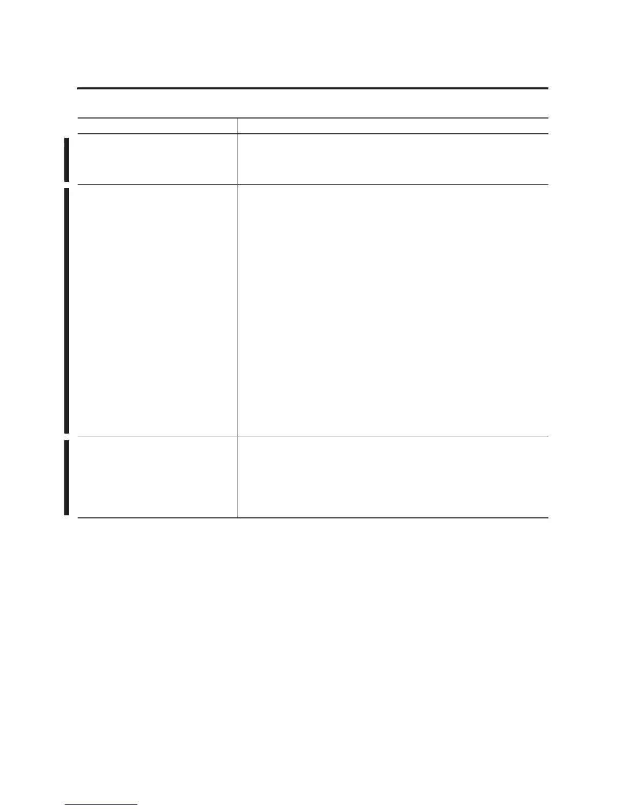
Did you already update the firmware of the
series E modules?
Did you already update the firmware of the series E modules?
• Yes — Go to step 6.
• No — Continue with step 5.
5. Update the firmware of the series E
modules.
A. Remove the 1757-SRM module from the secondary chassis.
B. Set the address of each series E module to the address of its corresponding series D
module plus one.
C. Replace each series D module with the corresponding series E module.
Important: Make sure you connect the correct ControlNet tap to each module.
D. Use ControlFlash software and update the firmware of each series E module.
E. Remove the series E modules from the secondary chassis and set their addresses to
match the original series D modules.
F. Repeat steps B-E for the second set of series E modules.
G. Put the secondary SRM back into the secondary chassis.
H. Put one set of series E modules into the secondary chassis.
Important: Make sure that you use the correct address, slot, and ControlNet tap for
each module.
I. Go to step 7.
6. Replace the CNB modules in the
secondary chassis.
Replace the CNB/D modules in the secondary chassis with series E modules. As you
replace the modules:
• make sure that you set each module to the same address as the module that it is
replacing.
• make sure that you connect the correct ControlNet tap. To avoid connecting the wrong
tap, replace the modules one at a time and reconnect the ControlNet tap.
Action Details

 Loading...


