90 Rockwell Automation Publication 1766-UM001I-EN-P - June 2015
Chapter 5 Using the LCD
:
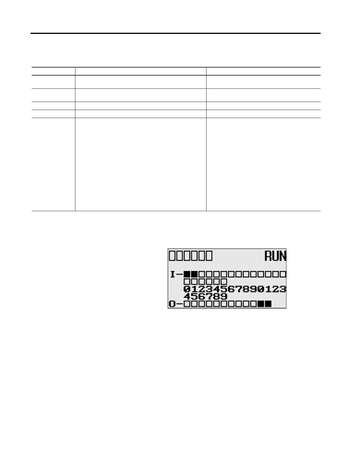
LCD Default Screen – I/O Status Screen
.
This is the default screen of the display, allowing you to monitor controller and
I/O Status. For more information on the I/O Status screen, see I/O Status on
page 93.
Main Menu Items
Menu Item Description For details, refer to
I/O Status Displays the I/O Status screen, which shows the I/O status of the
embedded digital I/O.
I/O Status on page 93
Monitoring Allows you to view and change the data value of a bit and an
integer file.
Monitor User Defined Target Files on page 95
Monitoring Integer Files on page 100
Mode Switch Allows you to change the mode switch selection. Using the Mode Switch on page 112
User Display Displays the user defined LCD screen Using a User Defined LCD Screen on page 115
Advanced Set Allows you to configure or view the following:
• Change the key in mode for value entry for a trim pot.
• Use the communications toggle functionality.
• View and change the Ethernet network configuration.
• Change the data value of trim pots.
• View system information, such as OS series and firmware
version.
• User communication EEPROM functionality.
• Change LCD contrast and backlight option.
• Modbus RTU Slave Node Address
• Changing Key In Mode on page 118
• Using Communications Toggle Functionality on
page 120
• Viewing Ethernet Status on page 120
• Using Trim Pots on page 131
• I/O Status on page 93
• Saving/Loading Communication EEPROM on page 136
• LCD setup on page 139
• See Protocol Configuration on page 142
COM
M0
CO
M
M 1
DCOMM
BA
T
.
L
O
U-
DI
S
P
COM
M
2

 Loading...


