38 Rockwell Automation Publication 1766-UM001I-EN-P - June 2015
Chapter 3 Wire Your Controller
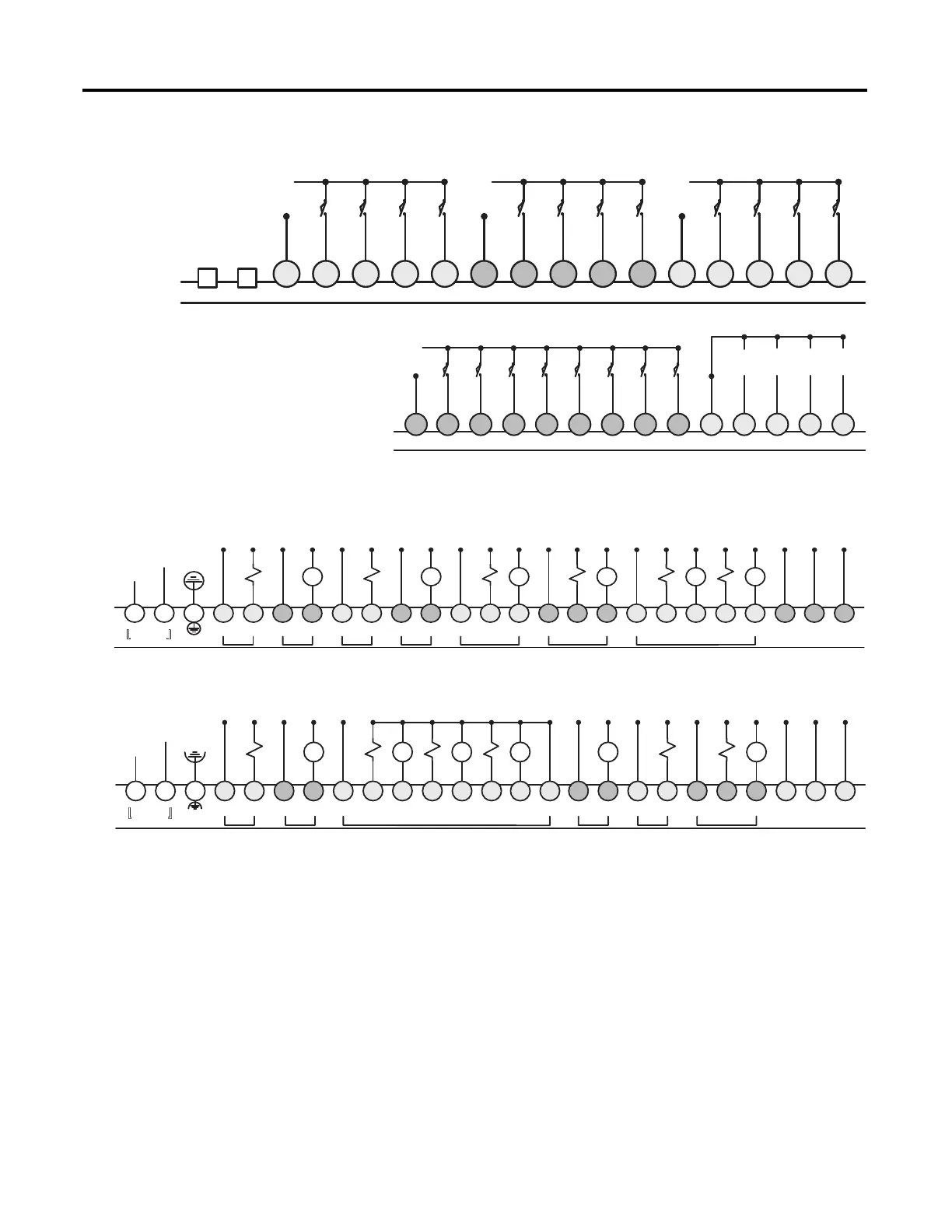
Figure 10 - 1766-L32BXB/L32BXBA Sourcing Input Wiring Diagram
Figure 11 - 1766-L32AWA/L32AWAA and 1766-L32BWA/L32BWAA Output Wiring
Diagram
Figure 12 - 1766-L32BXB/L32BXBA Output Wiring Diagram
Controller I/O Wiring
Minimizing Electrical Noise
Because of the variety of applications and environments where controllers are
installed and operating, it is impossible to ensure that all environmental noise will
be removed by input filters. To help reduce the effects of environmental noise,
install the MicroLogix 1400 system in a properly rated (for example, NEMA)
enclosure. Make sure that the MicroLogix 1400 system is properly grounded.
A system may malfunction due to a change in the operating environment after a
period of time. We recommend periodically checking system operation,
particularly when new machinery or other noise sources are installed near the
MicroLogix 1400 system.
DC
COM 0
+DCa
-DCa
IN0 IN1 IN2 IN3
DC
COM 1
+DCb
-DCb
IN4 IN5 IN6 IN7
DC
COM 2
+DCc
-DCc
IN8 IN9 IN10 IN11
NOT
USED
NOT
USED
DC
COM 3
+DCd
-DCd
IN12 IN13 IN14 IN15
IN17 IN18 IN19IN16
COM
ANA
A
GND AIN0
IV0(+) IV1(+) IV2(+) IV3(+)
A
IN1 AIN2 AIN3
1766-L32BXBA only
L1
L2
-DCa L1a L2a A
OUT0
A
OUT1
A
GND
L1 L2/N
100-240 VAC
DC0
VAC
OUT0 DC1
VAC
OUT1 DC2
VAC
OUT2 DC3
VAC
OUT3 DC4
VAC
OUT4 OUT5 DC5
VAC
OUT6 OUT7 DC6
VAC
OUT8 OUT9 OUT10 OUT11
COM
ANA
OV0 OV1
+DCa L1b L2b L1c L2c L1d L2d L3d L1e L2e L3e L1f L2f L3f L4f L5f
CR CR CR CR CR CR
+DC
-DC
-DCa +DCb -DCb AOUT0 AOUT1AGND
+ 24V -
DC IN
DC0
VAC
OUT0 DC1
VAC
OUT1 VDC2 OUT2 OUT3 OUT4 OUT5 OUT6 OUT7 COM2 DC3
VAC
OUT8 DC4
VAC
OUT9 DC5
VAC
OUT10 OUT11
COM
ANA
OV0 OV1
+DCa +DCc -DCc +DCd -DCd +DCe -DCe +DCf -DCf -DCf
CR CR CR CR CRCR

 Loading...


