Rockwell Automation Publication 1766-UM001I-EN-P - June 2015 369
System Loading and Heat Dissipation Appendix H
Validating the System
The example systems shown in the tables below are verified to be acceptable
configurations. The systems are valid because:
• Calculated Current Values < Maximum Allowable Current Values
• Calculated System Loading < Maximum Allowable System Loading
System Loading Worksheet
The tables below are provided for system loading validation. See System Loading
Example Calculations on page 368.
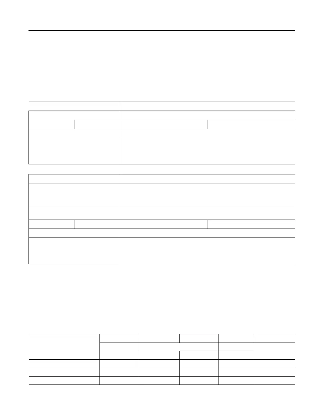
Current Loading
Validating Systems using 1766-L32AWA, or 1766-L32BXB
Maximum Allowable Values Calculated Values
Current: Current (Subtotal from Table on page 368.):
1225 mA @ 5V DC 1155 mA @ 24V DC 0 mA + 260 mA = 260 mA @ 5V DC 0 mA + 180 mA = 180 mA @ 24V DC
System Loading: System Loading:
33.845 W
= (260 mA x 5V) + (180 mA x 24V)
= (1,300 mW) + (4,320 mW)
= 5,620 mW
= 5.62 W
Validating Systems using 1766-L32BWA
Maximum Allowable Values Calculated Values
Current for Devices Connected to the +24V DC
Sensor Supply:
Sum of all sensor currents
250 mA @ 24V DC 140 mA @ 24V DC (example sensor value)
Current for MicroLogix Accessories and Expansion
I/O:
Current Values (Subtotal from Table ):
1225 mA @ 5V DC 1155 mA @ 24V DC 0 mA + 260 mA = 260 mA @ 5V DC 0 mA + 180 mA = 180 mA @ 24V DC
System Loading: System Loading:
39.845 W
= (140 mA x 24V) + (260 mA x 5V) + (180 mA x 24V)
= (3,360 mW) + (1,300 mW) + (4,320 mW)
= 8,980 mW
= 8.98 W
Calculating the Current for Expansion I/O
Catalog Number
(1)
n A B n x A n x B
Number of
Modules
Device Current Requirements Calculated Current
@ 5V DC (mA) @ 24V DC (mA) @ 5V DC (mA) @ 24V DC (mA)
1762-IA8 50 0
1762-IF4 40 50
1762-IF2OF2 40 105

 Loading...


