EasyManuals Logo

Allen-Bradley MicroLogix 1400 User Manual

Allen-Bradley MicroLogix 1400
404 pages
To Next Page IconTo Next Page
To Previous Page IconTo Previous Page
Page #30 background imageLoading...
Page #30 background image
16 Rockwell Automation Publication 1766-UM001I-EN-P - June 2015
Chapter 2 Install Your Controller
Schematic (Using ANSI/CSA Symbols)
Installing a Memory
Module
1. Remove the memory module port cover.
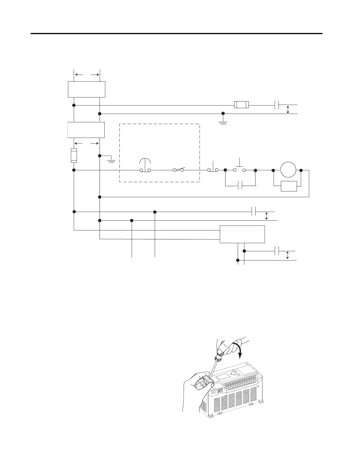
Emergency-Stop
Push Button
230V AC
Operation of either of these contacts will
remove power from the external I/O
circuits, stopping machine motion.
Fuse MCR
Fuse
MCR
MCR
MCR
Stop
Start
Line Terminals: Connect to terminals of Power
Supply (1766-L32AWA, 1766-L32AWAA,
1766-L32BWA, 1766-L32BWAA).
Line Terminals: Connect to 24V DC terminals of
Power Supply (1766-L32BXB, 1766-L32BXBA).
230V AC
Output
Circuits
Disconnect
Isolation
Transformer
115V AC or
230V AC
I/O Circuits
L1
L2
Master Control Relay (MCR)
Cat. No. 700-PK400A1
Suppressor
Cat. No. 700-N24
(Lo)
(Hi)
DC Power Supply. Use
NEC Class 2 for UL
Listing
.
X1 X2
115V AC or
230V AC
_
+
MCR
24 V DC
I/O
Circuits
Suppr.
Overtravel
Limit Switch
44565

Table of Contents

Other manuals for Allen-Bradley MicroLogix 1400

Questions and Answers:

Question and Answer IconNeed help?

Do you have a question about the Allen-Bradley MicroLogix 1400 and is the answer not in the manual?

Allen-Bradley MicroLogix 1400 Specifications

General IconGeneral
Processor32-bit
Expansion ModulesUp to 7 expansion I/O modules
Power Supply24V DC or 120/240V AC
Programming SoftwareRSLogix 500
Communication PortsEthernet, RS-232/RS-485 combo port
Controller TypeProgrammable Logic Controller (PLC)
SeriesMicroLogix
Digital Outputs12
Analog Inputs6 (embedded)
Analog Outputs2 (embedded)
High-Speed Counter6 high-speed counters
Pulse Output2 (embedded)
Ethernet PortYes

Related product manuals