Rockwell Automation Publication 1766-UM001I-EN-P - June 2015 23
Install Your Controller Chapter 2
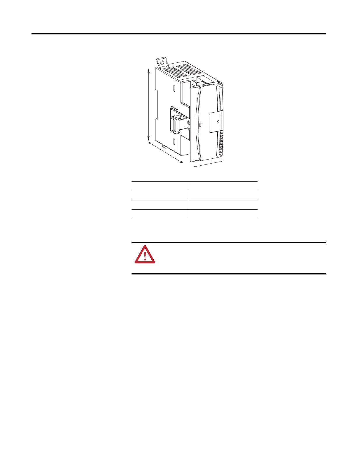
1762 Expansion I/O
Dimensions
Mounting 1762
Expansion I/O
DIN Rail Mounting
The module can be mounted using the following DIN rails:
• 35 x 7.5 mm (EN 50 022 - 35 x 7.5), or
• 35 x 15 mm (EN 50 022 - 35 x 15).
Before mounting the module on a DIN rail, close the DIN rail latch. Press the
DIN rail mounting area of the module against the DIN rail. The latch
momentarily opens and locks into place.
Use DIN rail end anchors (Allen-Bradley part number 1492-EA35 or
1492-EAH35) for vibration or shock environments. The following illustration
shows the location of the end anchors.
Dimension Measurement
A 90 mm (3.5 in.)
B 40 mm (1.57 in.)
C 87 mm (3.43 in.)
A
B
C
ATTENTION: During panel or DIN rail mounting of all devices, be
sure that all debris such as metal chips and wire stands, is kept
from falling into the module. Debris that falls into the module could
cause damage when the module is under power.

 Loading...


