EasyManuals Logo

Allen-Bradley MicroLogix 1400 User Manual

Allen-Bradley MicroLogix 1400
404 pages
To Next Page IconTo Next Page
To Previous Page IconTo Previous Page
Page #75 background imageLoading...
Page #75 background image
Rockwell Automation Publication 1766-UM001I-EN-P - June 2015 61
Communication Connections Chapter 4
mode. Hold down the OK key more than 5 seconds to toggle the communication
mode on the Main Menu screen.
Changing Communication Configuration
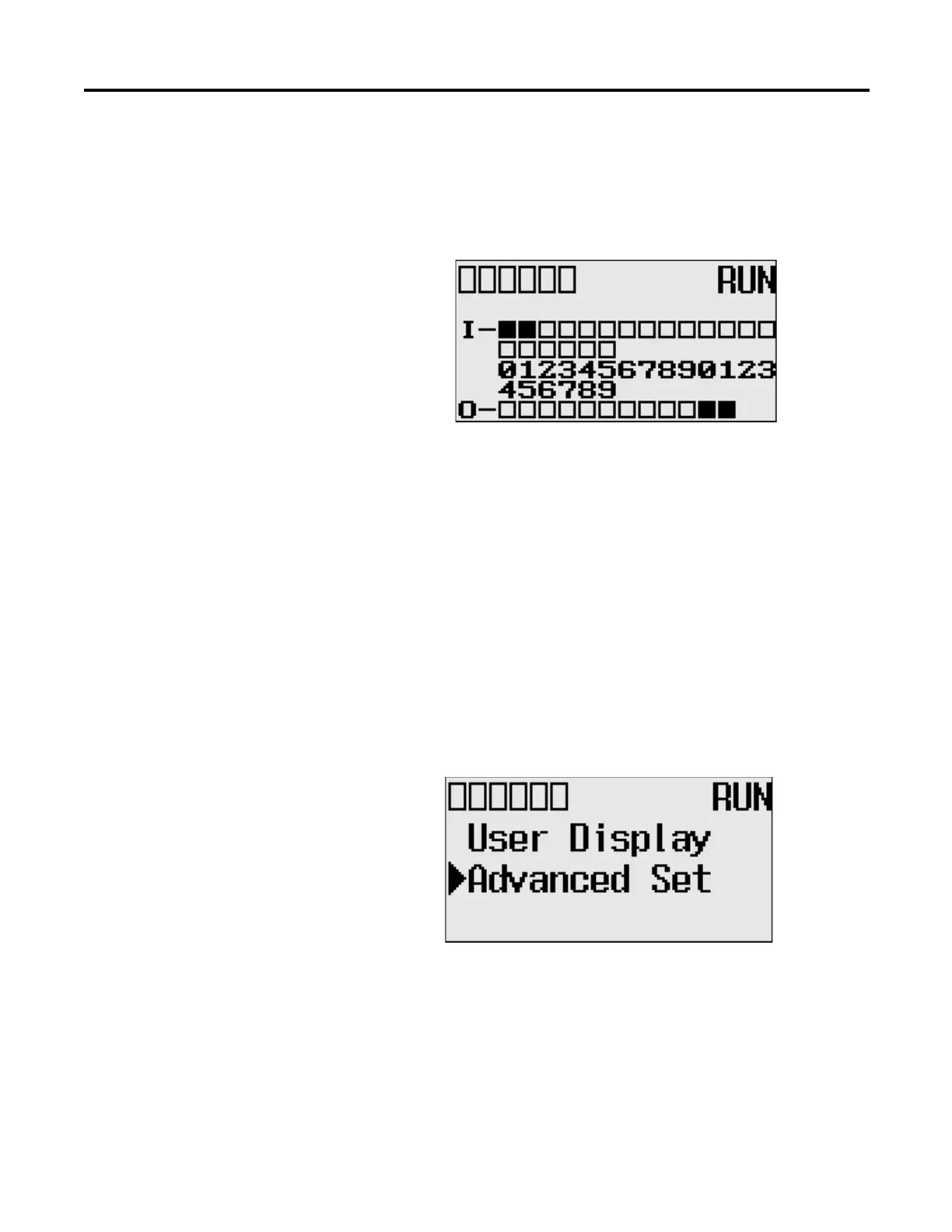
Follow the procedure below to change from the user-defined communication
configuration to the default communications mode and back. In this example, we
will start from the Main Menu screen of the LCD display, as shown below. If
necessary, press ESC repeatedly until you return to the Main Menu screen.
1. On the Main Menu screen, select Advance Set by using the Up and Down
keys on the LCD keypad. If the menu items shown in the figure below are
not displayed on the Main Menu screen, you need to scroll down the
screen by pressing the Down key.
TIP
The Communication Toggle Functionality only affects the
communication configuration of Channel 0.
COMM0
CO
MM 1
DCOM
M
BAT. LO
U-DISP
COM
M
2

Table of Contents

Other manuals for Allen-Bradley MicroLogix 1400

Questions and Answers:

Question and Answer IconNeed help?

Do you have a question about the Allen-Bradley MicroLogix 1400 and is the answer not in the manual?

Allen-Bradley MicroLogix 1400 Specifications

General IconGeneral
Processor32-bit
Expansion ModulesUp to 7 expansion I/O modules
Power Supply24V DC or 120/240V AC
Programming SoftwareRSLogix 500
Communication PortsEthernet, RS-232/RS-485 combo port
Controller TypeProgrammable Logic Controller (PLC)
SeriesMicroLogix
Digital Outputs12
Analog Inputs6 (embedded)
Analog Outputs2 (embedded)
High-Speed Counter6 high-speed counters
Pulse Output2 (embedded)
Ethernet PortYes

Related product manuals