Rockwell Automation Publication 1766-UM001I-EN-P - June 2015 181
Appendix
C
Troubleshooting Your System
This chapter describes how to troubleshoot your controller. Topics include:
• understanding the controller status indicators
• controller error recovery model
• analog expansion I/O diagnostics and troubleshooting
• calling Rockwell Automation for assistance
Understanding the
Controller Status Indicators
The MicroLogix 1400 provides three groups of status indicators:
• the status LEDs on the top of the controller,
• the status indicators on the LCD
• the I/O status indicators on the LCD.
Together they provide a mechanism to determine the current status of the
controller if a programming device is not present or available.
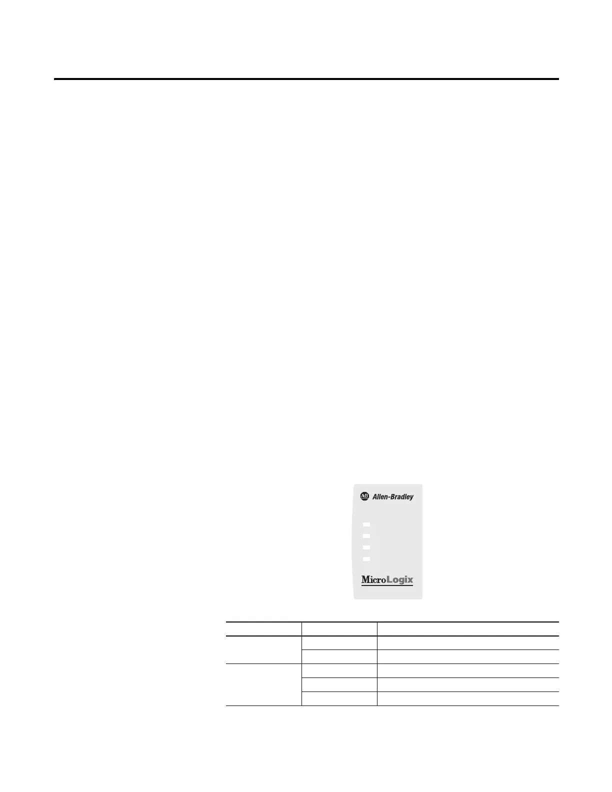
Controller Status LED Indicators
Figure 3 - Controller LED Location
Controller LED Indicators
LED Color Indicates
POWER off No input power, or power error condition
green Power on
RUN off Not executing the user program
green Executing the user program in run mode
green flashing Memory module transfer occurring
POWER
RUN
FAULT
FORCE
1400

 Loading...


