148 Rockwell Automation Publication 1766-UM001I-EN-P - June 2015
Chapter 6 Using Real-Time Clock and Memory Modules
RTC Battery Operation
The real-time clock uses the same replaceable battery that the controller uses. The
RTC Function File features a battery low indicator bit (RTC:0/BL), which
shows the status of the replacement battery. When the battery is low, the
indicator bit is set (1). This means that the battery wire connector could be
disconnected or if the battery is connected, the battery may be ready to fail in the
next two weeks. In the latter case, the replacement battery needs to be replaced
with a new one. When the battery low indicator bit is clear (0), the battery level is
acceptable.
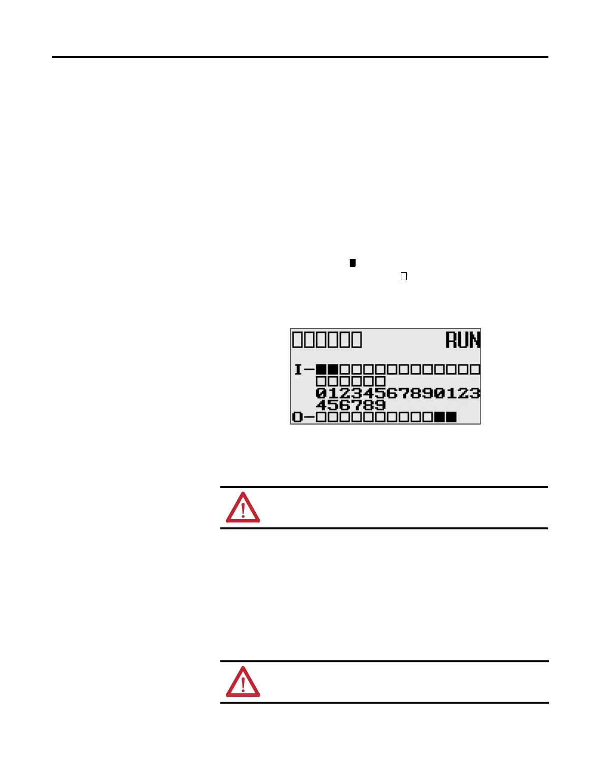
The Battery Low (BAT.LO) indicator on the LCD display of the controller also
shows the status of the replaceable battery. When the battery is low, the indicator
is displayed as a solid rectangle ( ). When the battery level is acceptable, the
indicator is displayed as an empty rectangle ( ), as shown below.
If the RTC battery is low and the controller is powered, the RTC operates
normally. If the controller power is removed and the RTC battery is low, RTC
data is lost.
Memory Module Operation
The memory module supports the following features:
• User Program, User Data, Datalog and Recipe Back-up
• User Program Compare
• Data File Download Protection
• Memory Module Write Protection
• Removal/Insertion Under Power
ATTENTION: Operating with a low battery indication for more
than 2 weeks may result in invalid RTC data unless power is on
continuously.
CO
MM0
CO
MM 1
DC
OM
M
BA
T
.
LO
U-
DISP
CO
M
M
2
ATTENTION: Electrostatic discharge can damage the Memory
Module. Do not touch the connector pins or other sensitive areas.

 Loading...


