Rockwell Automation Publication 1766-UM001I-EN-P - June 2015 17
Install Your Controller Chapter 2
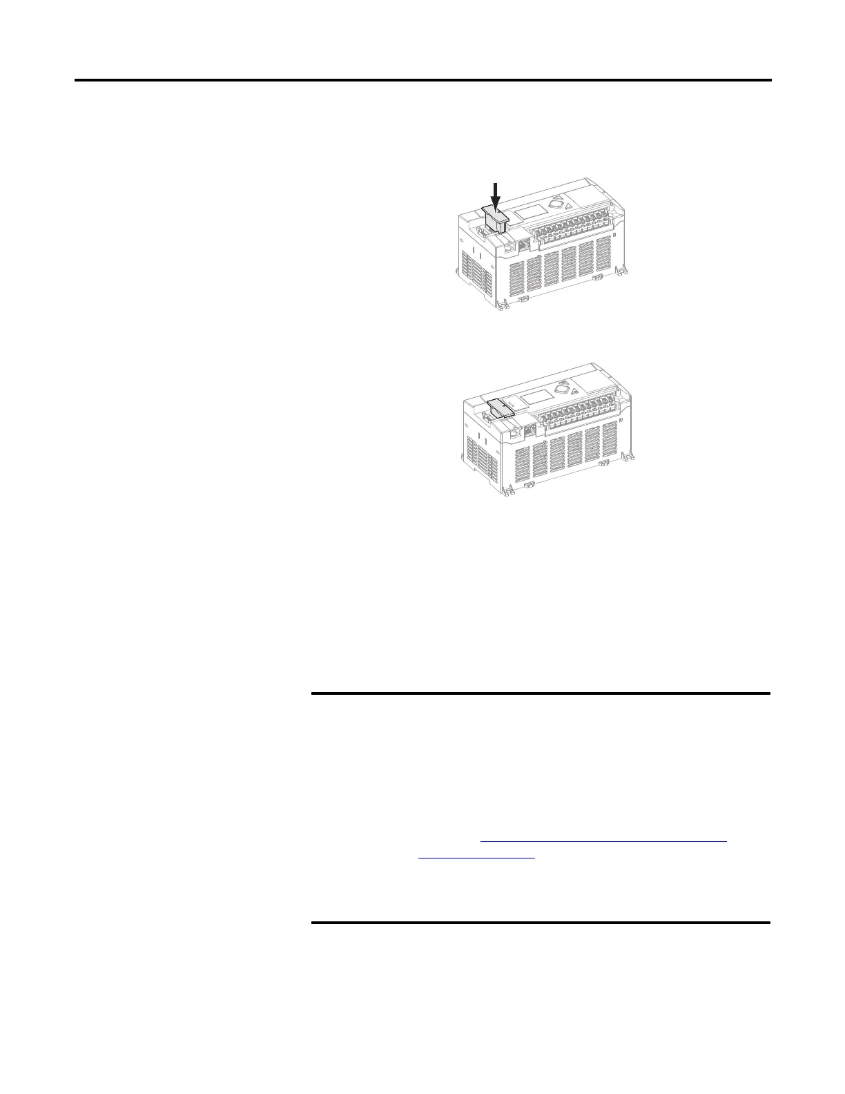
2. Align the connector on the memory module with the connector pins on
the controller.
3. Firmly seat the memory module into the controller.
4. Use a screwdriver as in step 1 to remove the memory module in the future.
Using the Battery
The MicroLogix 1400 controller is equipped with a replaceable battery (catalog
number 1747-BA). The Battery Low indicator on the LCD display of the
controller shows the status of the replaceable battery. When the battery is low, the
indicator is set (displayed as a solid rectangle). This means that either the battery
wire connector is disconnected, or the battery may fail within 2 weeks if it is
connected.
The MicroLogix 1400 controller ships with the battery wire connector
connected.
Ensure that the battery wire connector is inserted into the connector
port if your application needs battery power. For example, when using
a real-time clock (RTC).
Replacing the battery when the controller is powered down will lose
all user application memory. Replace the battery when the controller is
powered on.
Refer to the SLC 500 Lithium Battery Installation Instructions,
publication 1747-IN515, for more information on installation, handling,
usage, storage, and disposal of the battery.
See RTC Battery Operation on page 148, for more information on the
use of the battery in relation with RTC.

 Loading...


