EasyManuals Logo

Allen-Bradley MicroLogix 1400 User Manual

Allen-Bradley MicroLogix 1400
404 pages
To Next Page IconTo Next Page
To Previous Page IconTo Previous Page
Page #156 background imageLoading...
Page #156 background image
142 Rockwell Automation Publication 1766-UM001I-EN-P - June 2015
Chapter 5 Using the LCD
Protocol Configuration
The following section provides a step-by-step guide on how to change the
Modbus Node address.
Modbus RTU Slave Node Address
The user can set the Modbus RTU Slave Node address for Channel 0 or 2.
Changing the Modbus RTU Slave Node address
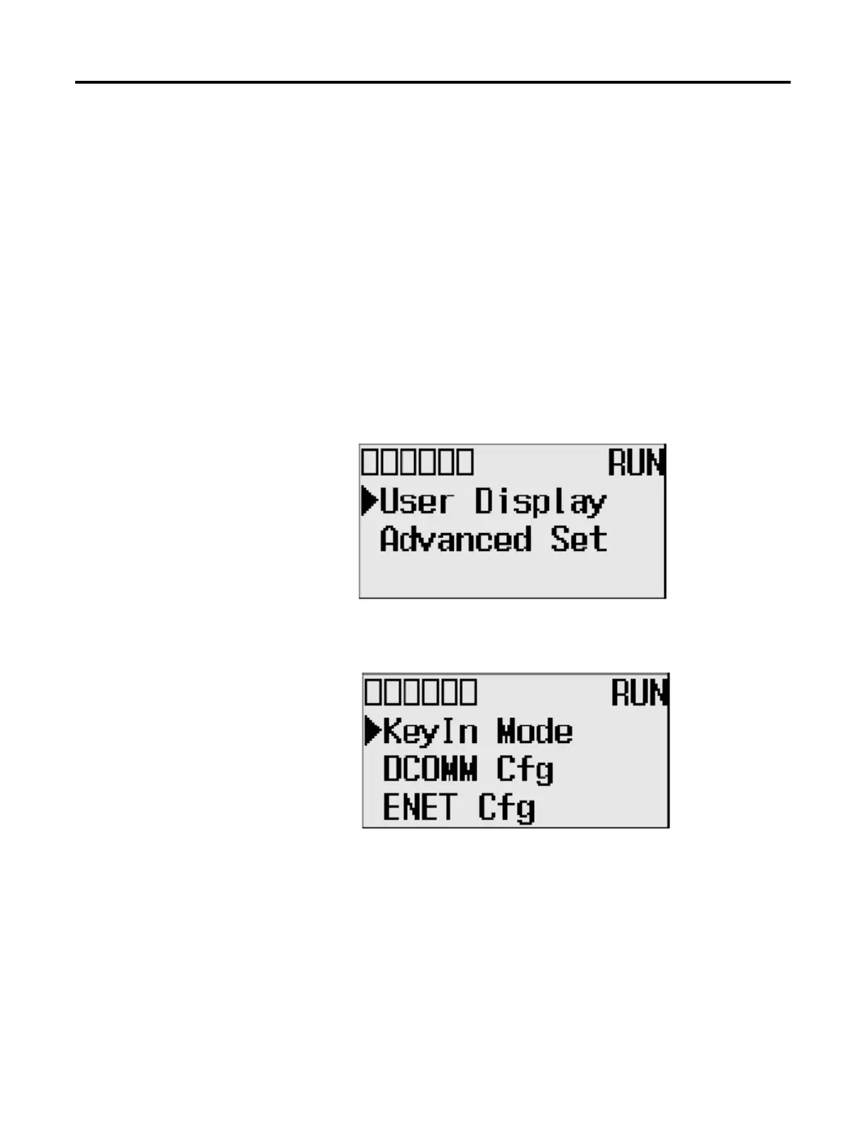
1. On the Main Menu screen, select Advanced Set by using the Up or Down
arrow key on the LCD keypad. If the menu items shown in the figure are
not displayed on the Main Menu screen below, you need to scroll down the
screen by pressing the Down arrow key.
2. Then, press the OK key on the LCD keypad. The Advanced Settings
Menu screen is displayed.
TIP
The node address change will only be applicable after a power cycle.

Table of Contents

Other manuals for Allen-Bradley MicroLogix 1400

Questions and Answers:

Question and Answer IconNeed help?

Do you have a question about the Allen-Bradley MicroLogix 1400 and is the answer not in the manual?

Allen-Bradley MicroLogix 1400 Specifications

General IconGeneral
Processor32-bit
Expansion ModulesUp to 7 expansion I/O modules
Power Supply24V DC or 120/240V AC
Programming SoftwareRSLogix 500
Communication PortsEthernet, RS-232/RS-485 combo port
Controller TypeProgrammable Logic Controller (PLC)
SeriesMicroLogix
Digital Outputs12
Analog Inputs6 (embedded)
Analog Outputs2 (embedded)
High-Speed Counter6 high-speed counters
Pulse Output2 (embedded)
Ethernet PortYes

Related product manuals