28 Rockwell Automation Publication 1766-UM001I-EN-P - June 2015
Chapter 3 Wire Your Controller
• Separate wiring by signal type. Bundle wiring with similar electrical
characteristics together.
• Separate input wiring from output wiring.
• Label wiring to all devices in the system. Use tape, shrink-tubing, or other
dependable means for labeling purposes. In addition to labeling, use
colored insulation to identify wiring based on signal characteristics. For
example, you may use blue for DC wiring and red for AC wiring.
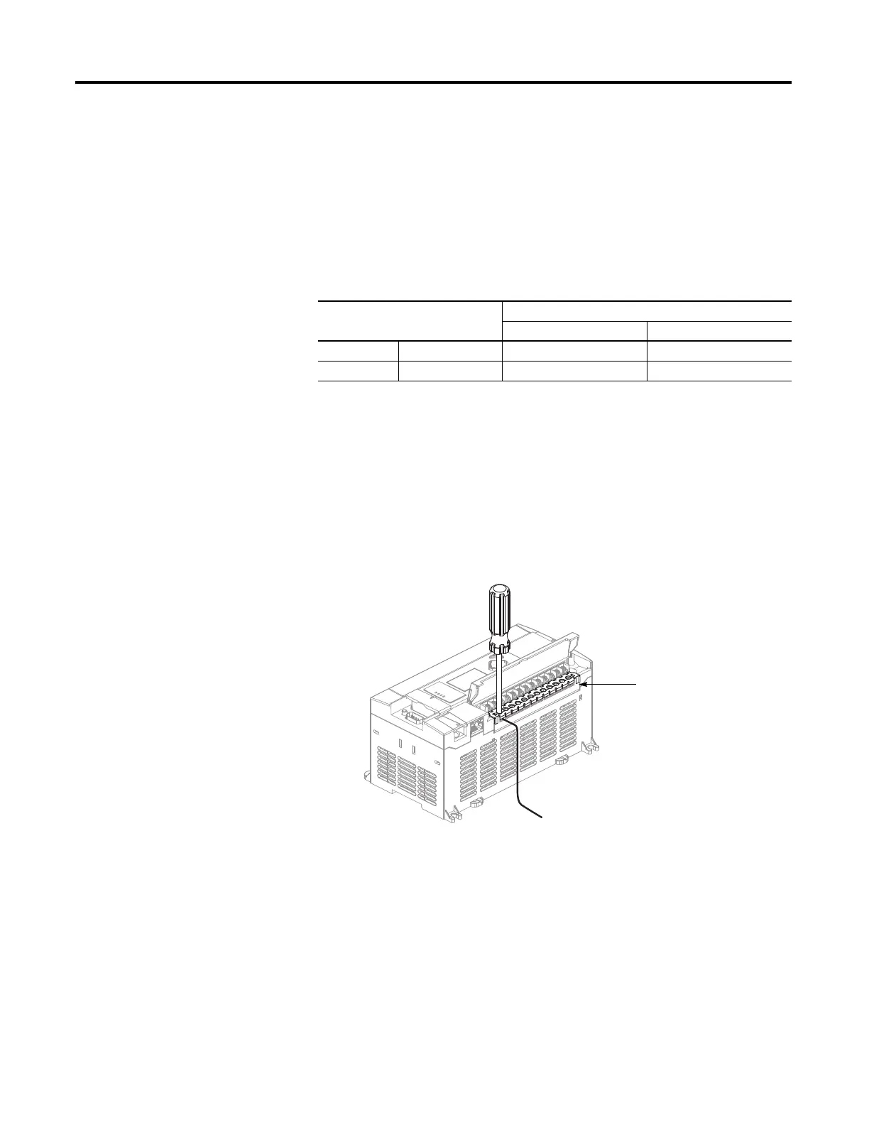
Wire without Spade Lugs
When wiring without spade lugs, it is recommended to keep the finger-safe covers
in place. Loosen the terminal screw and route the wires through the opening in
the finger-safe cover. Tighten the terminal screw making sure the pressure plate
secures the wire.
Wire with Spade Lugs
The diameter of the terminal screw head is 5.5 mm (0.220 in.). The input and
output terminals of the MicroLogix 1400 controller are designed for a 6.35 mm
(0.25 in.) wide spade (standard for #6 screw for up to 14 AWG) or a 4 mm
(metric #4) fork terminal.
Wire Requirements
Wire Type Wire Size (2 wire maximum per terminal screw)
1 wire per terminal 2 wire per terminal
Solid Cu-90°C (194°F) #12 to #20 AWG #16 to #20 AWG
Stranded Cu-90°C (194°F) #14 to #20 AWG #18 to #20 AWG
Wiring torque = 0.56 Nm (5.0 in-lb) rated

 Loading...


