Rockwell Automation Publication 1766-UM001I-EN-P - June 2015 25
Install Your Controller Chapter 2
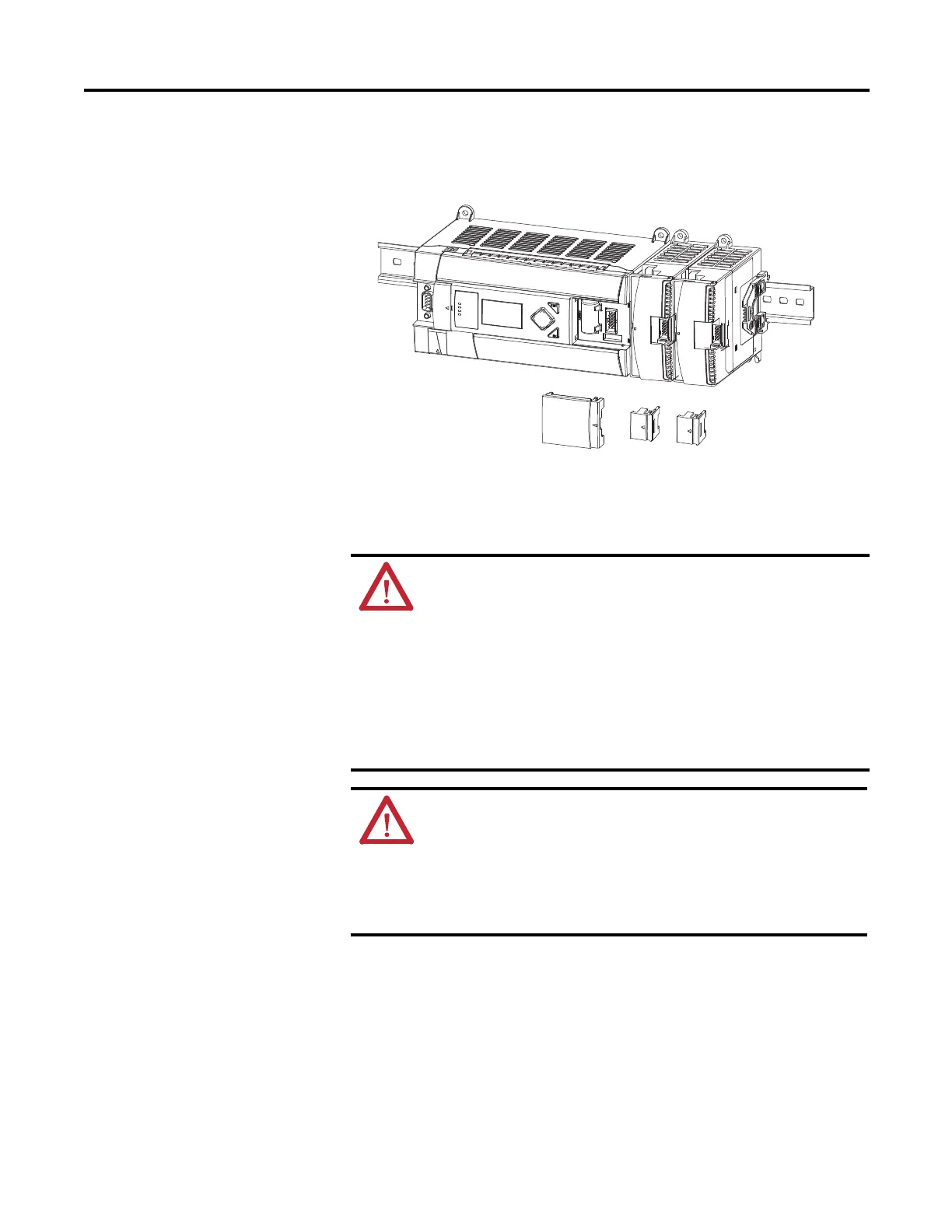
Connecting Expansion I/O
The expansion I/O module is attached to the controller or another I/O module
by means of a flat ribbon cable after mounting, as shown below.
Use the pull loop on the connector to disconnect modules. Do not pull
on the ribbon cable.
Up to seven expansion I/O modules can be connected to a controller.
ATTENTION: Remove power before removing or inserting an I/O
module. When you remove or insert a module with power applied,
an electrical arc may occur. An electrical arc can cause personal
injury or property damage by:
· sending an erroneous signal to your system’s field devices,
causing the controller to fault
· causing an explosion in a hazardous environment
Electrical arcing causes excessive wear to contacts on both the
module and its mating connector. Worn contacts may create electrical
resistance, reducing product reliability.
WARNING: EXPLOSION HAZARD
In Class I, Division 2 applications, the bus connector must be fully
seated and the bus connector cover must be snapped in place.
In Class I, Division 2 applications, all modules must be mounted in
direct contact with each other as shown on page 25. If DIN rail
mounting is used, an end stop must be installed ahead of the
controller and after the last 1762 I/O module.

 Loading...


