EasyManuals Logo

Allen-Bradley MicroLogix 1400 User Manual

Allen-Bradley MicroLogix 1400
404 pages
To Next Page IconTo Next Page
To Previous Page IconTo Previous Page
Page #146 background imageLoading...
Page #146 background image
132 Rockwell Automation Publication 1766-UM001I-EN-P - June 2015
Chapter 5 Using the LCD
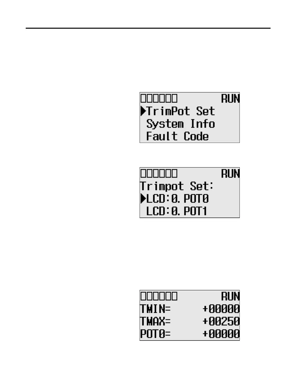
Changing Data Value of a Trim Pot
Follow these steps to change the data value of a trim pot, either POT0 or POT1.
1. On the Main Menu screen, select trim pot Set by using the Up and Down
keys on the LCD keypad.
2. Then, press the OK key on the LCD keypad. The Trim Pot Select screen is
displayed, as shown below.
The last trim pot whose data value you changed is selected by default. If
you are accessing to this screen for the first time, POT0 is selected by
default.
3. Select a trim pot, either POT0 or POT1, whose data value you want to
change using the Up and Down keys on the LCD keypad. In this example,
we will select POT0.
4. Then, press the OK key on the LCD keypad. The Trim Pot 0 screen is
displayed, as shown below.

Table of Contents

Other manuals for Allen-Bradley MicroLogix 1400

Questions and Answers:

Question and Answer IconNeed help?

Do you have a question about the Allen-Bradley MicroLogix 1400 and is the answer not in the manual?

Allen-Bradley MicroLogix 1400 Specifications

General IconGeneral
Processor32-bit
Expansion ModulesUp to 7 expansion I/O modules
Power Supply24V DC or 120/240V AC
Programming SoftwareRSLogix 500
Communication PortsEthernet, RS-232/RS-485 combo port
Controller TypeProgrammable Logic Controller (PLC)
SeriesMicroLogix
Digital Outputs12
Analog Inputs6 (embedded)
Analog Outputs2 (embedded)
High-Speed Counter6 high-speed counters
Pulse Output2 (embedded)
Ethernet PortYes

Related product manuals