EasyManuals Logo

Allen-Bradley MicroLogix 1400 User Manual

Allen-Bradley MicroLogix 1400
404 pages
To Next Page IconTo Next Page
To Previous Page IconTo Previous Page
Page #126 background imageLoading...
Page #126 background image
112 Rockwell Automation Publication 1766-UM001I-EN-P - June 2015
Chapter 5 Using the LCD
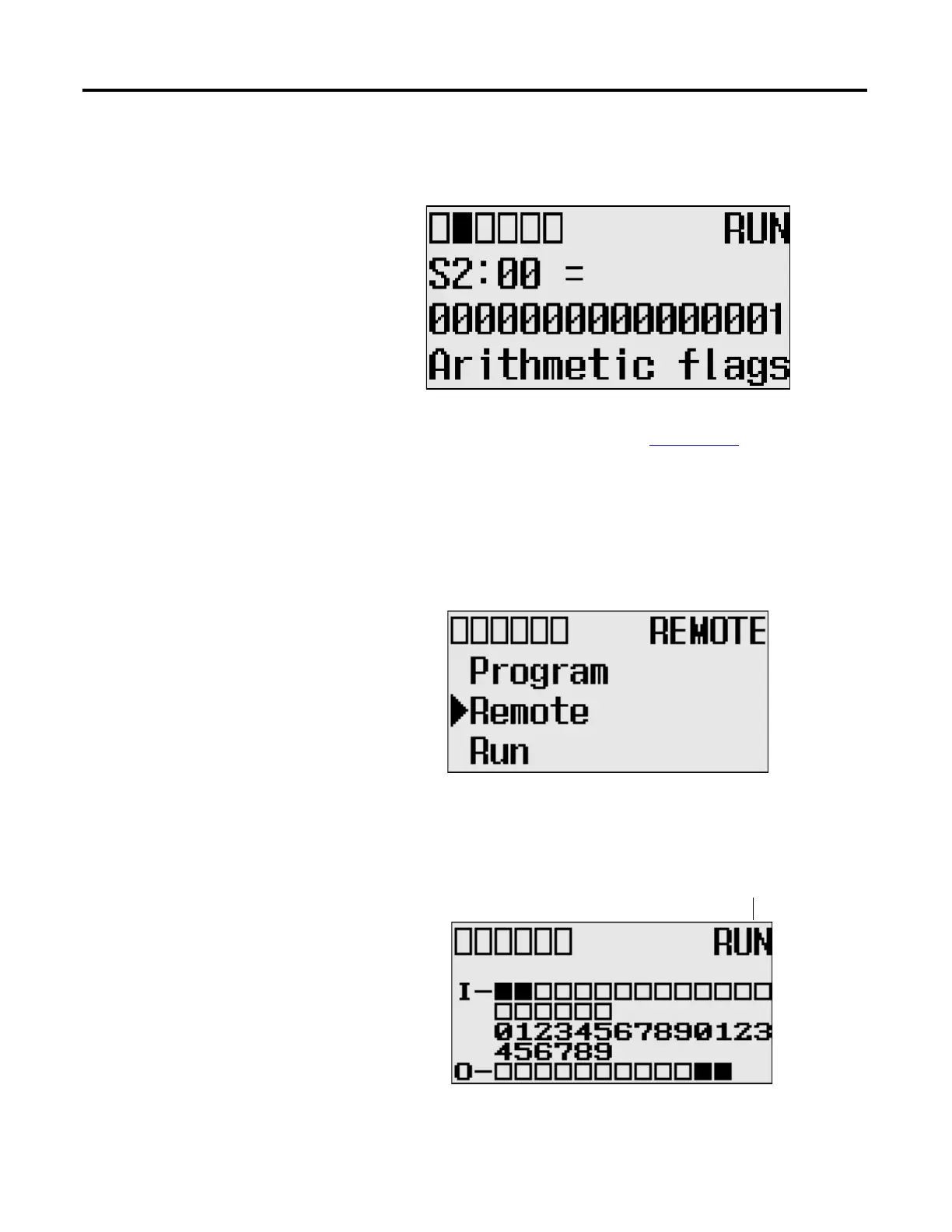
The format string on the third line is displayed as decimal, hexadecimal or binary
for each word element, depending on what each elements means.
For more information, see the MicroLogix 1400 Programmable Controllers
Instruction Set Reference Manual, publication 1766-RM001
.
Using the Mode Switch
The MicroLogix 1400 provides the controller mode switch on the LCD. The
possible positions of the mode switch are PROGRAM, REMOTE, and RUN.
You can change mode switch position using the Mode Switch screen on the LCD,
as shown below. In this example, the mode switch position is set to REMOTE.
All the built-in LCD screens except the Boot Message screen display the current
mode switch position, at their top right portion, as shown below. In this example,
the mode switch position is set to RUN.
Current Mode Switch Position

Table of Contents

Other manuals for Allen-Bradley MicroLogix 1400

Questions and Answers:

Question and Answer IconNeed help?

Do you have a question about the Allen-Bradley MicroLogix 1400 and is the answer not in the manual?

Allen-Bradley MicroLogix 1400 Specifications

General IconGeneral
Processor32-bit
Expansion ModulesUp to 7 expansion I/O modules
Power Supply24V DC or 120/240V AC
Programming SoftwareRSLogix 500
Communication PortsEthernet, RS-232/RS-485 combo port
Controller TypeProgrammable Logic Controller (PLC)
SeriesMicroLogix
Digital Outputs12
Analog Inputs6 (embedded)
Analog Outputs2 (embedded)
High-Speed Counter6 high-speed counters
Pulse Output2 (embedded)
Ethernet PortYes

Related product manuals