Rockwell Automation Publication 1766-UM001I-EN-P - June 2015 1
Chapter
1
Hardware Overview
Hardware Features
The Bulletin 1766, MicroLogix 1400 programmable controller contains a power
supply, input and output circuits, a processor, an isolated combination
RS-232/485 communication port, an Ethernet port, and a non-isolated RS-232
communication port. Each controller supports 32 discrete I/O points(20 digital
inputs, 12 discrete outputs) and 6 analog I/O points(4 analog inputs and 2 analog
outputs : 1766-L32BWAA, 1766-AWAA and 1766-BXBA only).
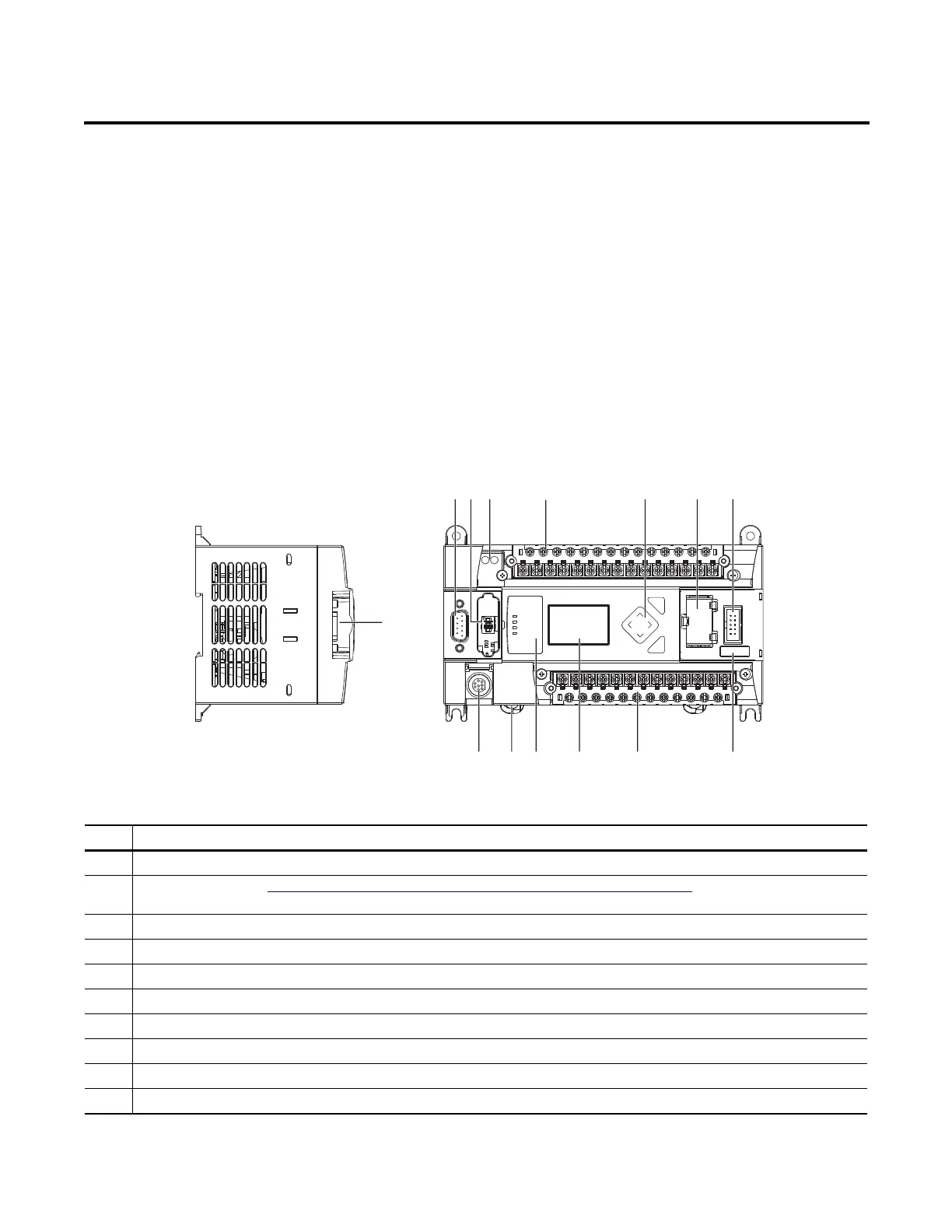
The hardware features of the controller are shown below.
Description
1 Comm port 2 - 9-pin D-Shell RS-232C connector
2 Memory module (refer to MicroLogix 1400 Memory Module Installation Instructions, publication 1766-IN010A
for instructions on installing the
memory module).
3 User 24V (for 1766-BWA and 1766-BWAA only)
4 Input terminal block
5 LCD Display Keypad (ESC, OK, Up, Down, Left, Right)
6 Battery compartment
7 1762 expansion bus connector
8 Battery connector
9 Output terminal block
10 LCD Display
1
ESC
OK
256 7
8
9101113 12
43
4451544514
Left side view Top view

 Loading...


